1NZ-FXE FUEL FUEL INJECTOR INSTALLATION
PROCEDURE

 23250
1.INSTALL FUEL INJECTOR ASSEMBLY
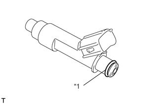
Apply a light coat of gasoline or spindle oil to new O-rings, and then install one onto each fuel injector.
| *1 | O-ring |
Apply a light coat of gasoline or spindle oil to the contact surfaces of the new O-ring on each fuel injector assembly.
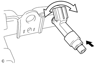
While turning the fuel injector assembly left and right, install it onto the fuel delivery pipe sub-assembly.

|
Push |

|
Turn |
- NOTICE:
- ·
Make sure that the O-ring is not cracked or jammed when installing the injector (See page Engine / Hybrid System>1NZ-FXE FUEL>FUEL SYSTEM>PRECAUTION).
·If a component has been dropped or subjected to a strong impact, replace it.
- HINT:
-
Perform "Inspection After Repairs" after replacing the fuel injector assembly (See page Engine / Hybrid System>1NZ-FXE (ENGINE CONTROL)>SFI SYSTEM (w/o Canister Pump Module)>INITIALIZATION).
Check that the fuel injector rotates smoothly. If the fuel injector does not rotate, replace the O-ring.
23291
2.INSTALL INJECTOR VIBRATION INSULATOR
Install 4 new injector vibration insulators onto the cylinder head.
23891
3.INSTALL FUEL DELIVERY SPACER
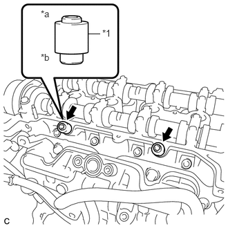
Install the 2 fuel delivery spacers onto the cylinder head.
| *1 | Fuel Delivery Spacer |
| *a | Fuel Delivery Pipe Side |
| *b | Cylinder Head Side |
- NOTICE:
-
Install the fuel delivery spacer in the correct direction.
23814B
4.INSTALL FUEL DELIVERY PIPE
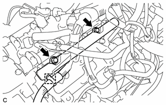
Install the fuel delivery pipe with the 4 fuel injector assemblies and install the 2 bolts.
- Torque:
- 21 N*m (214 kgf*cm, 15 ft.*lbf)
- NOTICE:
- ·
Do not drop the fuel injectors when installing the fuel delivery pipe.
·Check that the fuel injector assemblies rotate smoothly after installing the fuel delivery pipe.
Engage the clamp to connect the wire harness.
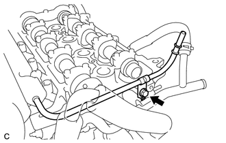
Install the bolt to secure the fuel delivery pipe.
- Torque:
- 10 N*m (102 kgf*cm, 7 ft.*lbf)
23901
5.CONNECT FUEL TUBE SUB-ASSEMBLY
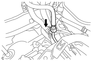
Push the tube connector into the pipe until the tube connector makes a "click" sound.
|
|
Push |
- NOTICE:
- ·
Before connecting the fuel tube connector and fuel delivery pipe, check that there is no damage or foreign matter on the connecting part of the fuel delivery pipe.
·After connecting the fuel tube connector and fuel delivery pipe, check that they are securely connected by trying to pull them apart.
23841B
6.INSTALL EFI FUEL PIPE CLAMP
Install the EFI fuel pipe clamp.
11201
7.INSTALL CYLINDER HEAD COVER SUB-ASSEMBLY
82121
8.CONNECT ENGINE WIRE (for LHD)
82121
9.CONNECT ENGINE WIRE (for RHD)
47220D
10.INSTALL BRAKE MASTER CYLINDER RESERVOIR ASSEMBLY
19500D
11.INSTALL NO. 1 IGNITION COIL
25680
12.INSTALL EGR VALVE WITH COOLER ASSEMBLY
13.CONNECT CABLE TO NEGATIVE AUXILIARY BATTERY TERMINAL
- NOTICE:
-
When disconnecting the cable, some systems need to be initialized after the cable is reconnected (See page General>INTRODUCTION>REPAIR INSTRUCTION>INITIALIZATION).
58165F
14.INSTALL FRONT FLOOR COVER RH
15.INSPECT FOR FUEL LEAK
16.INSPECT FOR ENGINE OIL LEAK