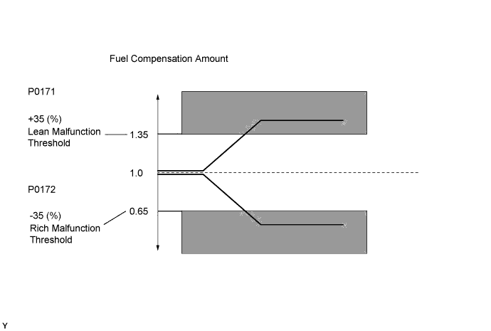
DTC P0171 System Too Lean (Bank 1) |
DTC P0172 System Too Rich (Bank 1) |
| DTC No. | DTC Detection Condition | Trouble Area |
| P0171 | With a warm engine and stable air fuel ratio feedback, fuel trim is too lean (2 trip detection logic). |
|
| P0172 | With a warm engine and stable air fuel ratio feedback, fuel trim is too rich (2 trip detection logic). |
|
| 1.CHECK ANY OTHER DTCS OUTPUT (IN ADDITION TO DTC P0171 OR P0172) |
Connect the intelligent tester to the DLC3.
Turn the ignition switch to ON.
Turn the tester on.
Enter the following menus: Powertrain / Engine and ECT / DTC.
Read the DTCs.
| Result | Proceed to |
| DTC P0171 or P0172 is output | A |
| DTC P0171 or P0172 and other DTCs are output | B |
|
| ||||
| A | |
 |
| 2.PERFORM ACTIVE TEST USING INTELLIGENT TESTER (AIR FUEL RATIO CONTROL) |
Connect the intelligent tester to the DLC3.
Start the engine.
Turn the tester on.
Warm up the engine at an engine speed of 2500 rpm for approximately 90 seconds.
Enter the following menus: Powertrain / Engine and ECT / Active Test / Control the Injection Volume for A/F Sensor.
Perform the "Control the Injection Volume for A/F Sensor" operation with the engine idling (press the RIGHT or LEFT button to change the fuel injection volume).
Monitor the output voltages of the air fuel ratio sensor (sensor 1) and heated oxygen sensor (sensor 2) (AFS Voltage B1 S1 and O2S B1 S2) displayed on the tester.
| Case | A/F Sensor (Sensor 1) Output Voltage | HO2 Sensor (Sensor 2) Output Voltage | Main Suspected Trouble Area |
| 1 |   |  | - |
| 2 |  | |
|
| 3 | | |
|
| Result | Proceed to |
| Case 1 | A |
| Case 2 | B |
| Case 3 | C |
|
| ||||
|
| ||||
| A | |
|
| 3.CONFIRM IF VEHICLE HAS RUN OUT OF FUEL IN PAST |
Has the vehicle run out of fuel in the past?
|
| ||||
| YES | |
|
| 4.PERFORM CONFIRMATION DRIVING PATTERN |
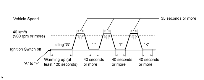
Connect the intelligent tester to the DLC3 (Procedure "A").
Turn the ignition switch to ON (Procedure "B").
Turn the tester on (Procedure "C").
Clear the DTCs (Click here) (Procedure "D").
Switch the ECM from normal mode to check mode (Click here) (Procedure "E").
Start the engine (Procedure "F").
Allow the engine to idle until the engine coolant temperature reaches 40°C (104°F) (Procedure "G").
Drive the vehicle at a vehicle speed of more than 40 km/h (25 mph) for 35 seconds or more (Procedure "H").
Allow the engine to idle for 40 seconds or more (Procedure "I").
Repeat procedures "G" through "I" described above at least 3 times (Procedure "J").
Allow the engine to idle for 40 seconds or more (Procedure "K").
| NEXT | |
|
| 5.CHECK WHETHER DTC OUTPUT RECURS (DTC P0171 OR P0172) |
Connect the intelligent tester to the DLC3.
Turn the ignition switch to ON.
Turn the tester on.
Enter the following menus: Powertrain / Engine and ECT / DTC.
Read the DTCs.
| Result | Proceed to |
| DTC P0171 or P0172 is output | A |
| DTC is not output | B |
|
| ||||
| A | |
|
| 6.CHECK FOR EXHAUST GAS LEAK |
Check for exhaust gas leakage.
|
| ||||
| OK | |
|
| 7.CHECK FUEL PRESSURE |
Check the fuel pressure .
|
| ||||
| OK | |
|
| 8.INSPECT INJECTOR ASSEMBLY (INJECTION VOLUME) |
Check the injection volume (Click here).
|
| ||||
| OK | |
|
| 9.INSPECT MASS AIR FLOW METER |
Inspect the mass air flow meter (Click here).
|
| ||||
| OK | |
|
| 10.READ VALUE USING INTELLIGENT TESTER (COOLANT TEMP) |
Connect the intelligent tester to the DLC3.
Turn the ignition switch to ON and turn the tester on.
Enter the following menus: Powertrain / Engine and ECT / Data List / Primary / Coolant Temp.
Read the Coolant Temp twice, when the engine is both cold and warmed up.
|
| ||||
| OK | |
|
| 11.CHECK PCV HOSE CONNECTIONS |
Check the PCV hose connections .
|
| ||||
| OK | |
|
| 12.CHECK INTAKE SYSTEM |
Check the intake system for vacuum leakage (Click here).
|
| ||||
| OK | |
|
| 13.CHECK IGNITION SYSTEM |
Inspect the ignition system (Click here).
|
| ||||
| OK | |
|
| 14.INSPECT AIR FUEL RATIO SENSOR (HEATER RESISTANCE) |
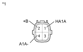 |
Disconnect the air fuel ratio sensor connector.
Measure the resistance according to the value(s) in the table below.
| Tester Connection | Condition | Specified Condition |
| 1 (HA1A) - 2 (+B) | 20°C (68°F) | 1.8 to 3.4 Ω |
| 1 (HA1A) - 4 (A1A-) | Always | 10 kΩ or higher |
| *1 | Component without harness connected (Air Fuel Ratio Sensor) |
Reconnect the air fuel ratio sensor connector.
|
| ||||
| OK | |
|
| 15.CHECK AIR FUEL RATIO SENSOR (POWER SOURCE) |
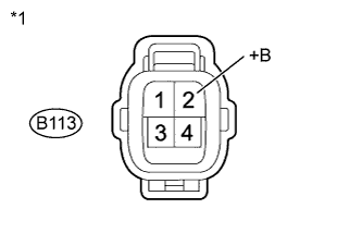 |
Disconnect the air fuel ratio sensor connector.
Measure the voltage according to the value(s) in the table below.
| Tester Connection | Switch Condition | Specified Condition |
| B113-2 (+B) - Body ground | Ignition switch ON | 11 to 14 V |
| *1 | Front view of wire harness connector (to Air Fuel Ratio Sensor) |
Reconnect the air fuel ratio sensor connector.
|
| ||||
| OK | |
|
| 16.CHECK HARNESS AND CONNECTOR (AIR FUEL RATIO SENSOR - ECM) |
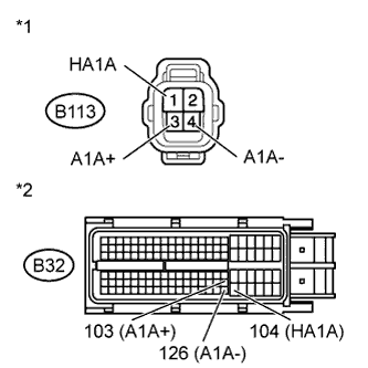 |
Disconnect the air fuel ratio sensor connector.
Disconnect the ECM connector.
Measure the resistance according to the value(s) in the table below.
| Tester Connection | Condition | Specified Condition |
| B113-1 (HA1A) - B32-104 (HA1A) | Always | Below 1 Ω |
| B113-3 (A1A+) - B32-103 (A1A+) | Always | Below 1 Ω |
| B113-4 (A1A-) - B32-126 (A1A-) | Always | Below 1 Ω |
| Tester Connection | Condition | Specified Condition |
| B113-1 (HA1A) or B32-104 (HA1A) - Body ground | Always | 10 kΩ or higher |
| B113-3 (A1A+) or B32-103 (A1A+) - Body ground | Always | 10 kΩ or higher |
| B113-4 (A1A-) or B32-126 (A1A-) - Body ground | Always | 10 kΩ or higher |
| *1 | Front view of wire harness connector (to Air Fuel Ratio Sensor) |
| *2 | Front view of wire harness connector (to ECM) |
Reconnect the ECM connector.
Reconnect the air fuel ratio sensor connector.
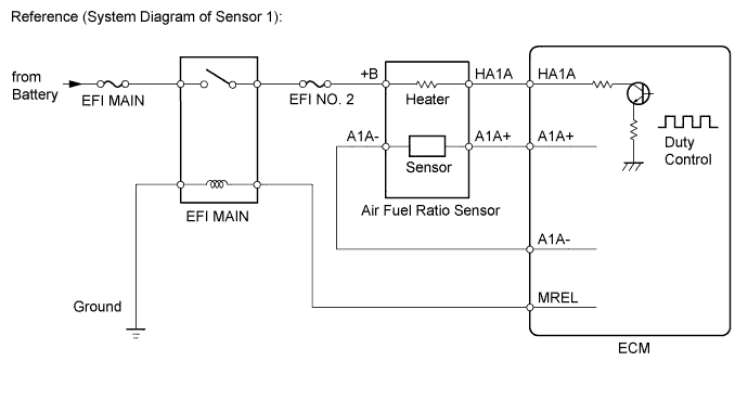
|
| ||||
| OK | |
|
| 17.REPLACE AIR FUEL RATIO SENSOR |
Replace the air fuel ratio sensor (Click here).
| NEXT | |
|
| 18.PERFORM CONFIRMATION DRIVING PATTERN |
Connect the intelligent tester to the DLC3 (Procedure "A").
Turn the ignition switch to ON (Procedure "B").
Turn the tester on (Procedure "C").
Clear the DTCs (Click here) (Procedure "D").
Switch the ECM from normal mode to check mode (Click here) (Procedure "E").
Start the engine (Procedure "F").
Allow the engine to idle until the engine coolant temperature reaches 40°C (104°F) (Procedure "G").
Drive the vehicle at a vehicle speed of more than 40 km/h (25 mph) for 35 seconds or more (Procedure "H").
Allow the engine to idle for 40 seconds or more (Procedure "I").
Repeat procedures "G" through "I" described above at least 3 times (Procedure "J").
Allow the engine to idle for 40 seconds or more (Procedure "K").
| NEXT | |
|
| 19.CHECK WHETHER DTC OUTPUT RECURS (DTC P0171 OR P0172) |
Connect the intelligent tester to the DLC3.
Turn the ignition switch to ON.
Turn the tester on.
Enter the following menus: Powertrain / Engine and ECT / DTC.
Read the DTCs.
| Result | Proceed to |
| DTC is not output | A |
| DTC P0171 or P0172 is output | B |
|
| ||||
| A | ||
 | ||
| ||
| 20.CHECK HARNESS AND CONNECTOR (AIR FUEL RATIO SENSOR - INTEGRATION RELAY) |
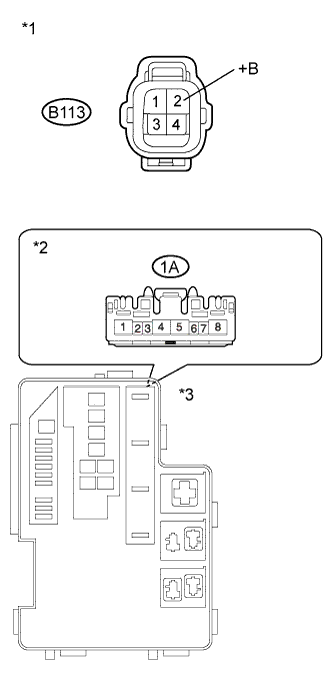 |
Disconnect the air fuel ratio sensor connector.
Remove the integration relay (EFI MAIN relay) from the engine room No. 1 relay block.
Disconnect the integration relay connector.
Measure the resistance according to the value(s) in the table below.
| Tester Connection | Condition | Specified Condition |
| B113-2 (+B) - 1A-4 | Always | Below 1 Ω |
| Tester Connection | Condition | Specified Condition |
| B113-2 (+B) or 1A-4 - Body ground | Always | 10 kΩ or higher |
| *1 | Front view of wire harness connector (to Air Fuel Ratio Sensor) |
| *2 | Front view of wire harness connector (to Integration Relay) |
| *3 | Engine Room No. 1 Relay Block |
Reconnect the air fuel ratio sensor connector.
Reconnect the integration relay connector.
Reinstall the integration relay.
|
| ||||
| OK | ||
| ||
| ||
| 21.CHECK FUEL LINE |
Check the fuel lines for leaks or blockage (Click here).
|
| ||||
| OK | ||
| ||
| ||

