AB60F AUTOMATIC TRANSMISSION / TRANSAXLE AUTOMATIC TRANSMISSION ASSEMBLY INSTALLATION
PROCEDURE

 36100
1.INSTALL TRANSFER ASSEMBLY
32000
2.INSTALL TORQUE CONVERTER CLUTCH ASSEMBLY
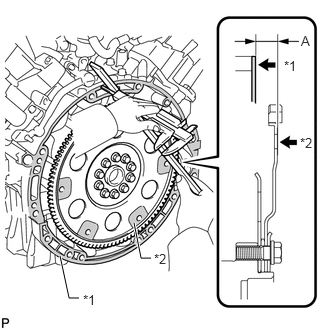
Using a vernier caliper and straightedge, measure dimension A between the transmission fitting surface of the engine *1 and the converter fitting surface of the drive plate *2. (#)
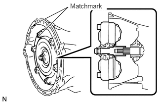
Aligning the matchmarks on the transmission case and torque converter, and then engage the splines of the input shaft and turbine runner.
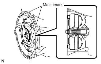
Engage the splines of the stator shaft and stator while turning the torque converter.
- HINT:
-
Turn the torque converter approximately 180°.
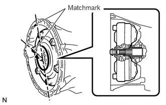
Turn the torque converter and align the matchmarks on the torque converter and transmission case to engage the key of the oil pump drive gear into the slot on the torque converter.
- NOTICE:
-
Do not push on the torque converter when aligning the matchmarks.
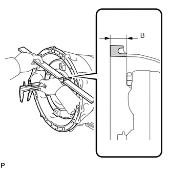
Using a vernier caliper and a straightedge, measure dimension B shown in the illustration and check that B is greater than A measured in the first step.
- Standard distance:
B = A + 1 mm (0.0394 in.) or more
33823A
3.INSTALL TRANSMISSION CONTROL CABLE BRACKET
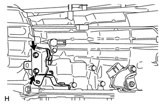
Install the transmission control cable bracket with the 2 bolts.
- Torque:
- 12 N*m (122 kgf*cm, 9 ft.*lbf)
4.INSTALL CONNECTOR CLAMP BRACKET
Install the front left bank oxygen sensor connector clamp bracket with the bolt.
- Torque:
- 8.0 N*m (82 kgf*cm, 71 in.*lbf)
Install the rear left bank oxygen sensor connector clamp bracket with the bolt.
- Torque:
- 29 N*m (296 kgf*cm, 21 ft.*lbf)
Install the front right bank oxygen sensor connector clamp bracket with the bolt.
- Torque:
- 8.0 N*m (82 kgf*cm, 71 in.*lbf)
35000
5.INSTALL AUTOMATIC TRANSMISSION ASSEMBLY
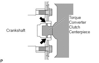
Apply clutch spline grease to the surface of the torque converter centerpiece that contacts the crankshaft.
- Clutch spline grease:
Toyota Genuine Clutch Spline Grease or equivalent
- Maximum grease amount:
Approximately 1 g (0.0353 oz.) Centerpiece
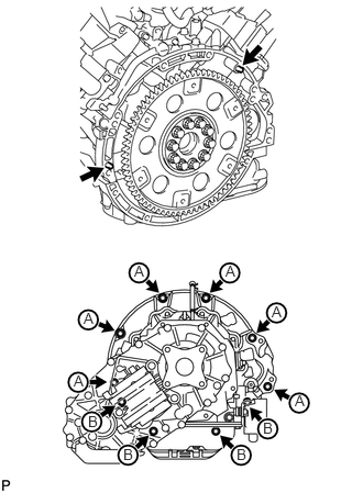
Confirm that the 2 knock pins are on the transaxle contact surface of the engine block before transaxle installation.
Install the transmission with the 10 bolts.
- Torque:
- for 17 mm head bolt A : 71 N*m (724 kgf*cm, 52 ft.*lbf)
- for 14 mm head bolt B : 37 N*m (377 kgf*cm, 27 ft.*lbf)
35104V
6.CONNECT BREATHER PLUG HOSE
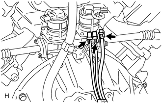
Connect the 3 breather plug hoses to the harness clamp bracket.
7.CONNECT WIRE HARNESS AND CONNECTOR
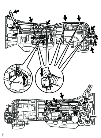
Connect the park/neutral start switch connector, 2 transmission wire connectors and 2 speed sensor connectors.
- HINT:
-
Push up the lever until the claw of the transmission wire connector makes a connection sound.
Connect the harness clamp with the bolt.
- Torque:
- 8.2 N*m (84 kgf*cm, 73 in.*lbf)
Connect the 3 connector clamps and 7 harness clamps.
Tilt up the automatic transmission.
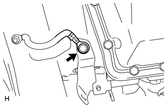
Connect the ground cable with the bolt.
- Torque:
- 5.5 N*m (56 kgf*cm, 49 in.*lbf)
12371
8.INSTALL REAR NO. 1 ENGINE MOUNTING INSULATOR
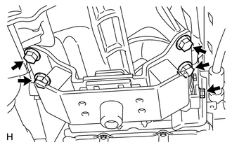
Install the rear No. 1 engine mounting insulator to the transmission with the 4 bolts.
- Torque:
- 40 N*m (407 kgf*cm, 30 ft.*lbf)
Install the rear engine mounting heat insulator with the bolt.
- Torque:
- 12 N*m (122 kgf*cm, 9 ft.*lbf)
51204
9.INSTALL NO. 3 FRAME CROSSMEMBER SUB-ASSEMBLY
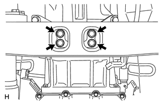
Install the No. 3 frame crossmember to the rear engine mounting insulator with the 4 bolts.
- Torque:
- 16 N*m (163 kgf*cm, 12 ft.*lbf)
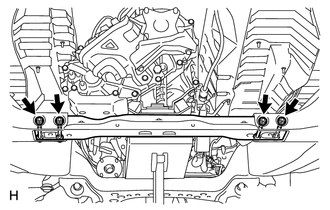
Install the No. 3 frame crossmember with the 4 bolts, 4 washers and 4 nuts.
- Torque:
- 110 N*m (1122 kgf*cm, 81 ft.*lbf)
32101A
10.INSTALL DRIVE PLATE AND TORQUE CONVERTER CLUTCH SETTING BOLT
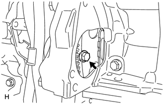
Turn the crankshaft to gain access to the 6 bolts and install the bolts while holding the crankshaft pulley set bolt with a wrench.
- Torque:
- 53 N*m (535 kgf*cm, 39 ft.*lbf)
- NOTICE:
-
First install the black colored bolt and then the remaining 5 bolts.
28100
11.INSTALL STARTER ASSEMBLY
Install the starter assembly (See page Engine / Hybrid System>3UR-FE STARTING>STARTER>INSTALLATION).
33820B
12.CONNECT TRANSMISSION CONTROL CABLE ASSEMBLY
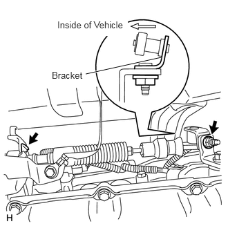
Connect the transmission control cable with a new clip and nut.
- Torque:
- 13 N*m (133 kgf*cm, 10 ft.*lbf)
- NOTICE:
-
When connecting the cable to the transmission control shaft lever, make sure the cable's L bracket faces the outside of the vehicle.
13.CONNECT WATER BY-PASS PIPE ASSEMBLY
14.INSTALL FRONT NO. 3 EXHAUST PIPE ASSEMBLY
17410
15.INSTALL FRONT EXHAUST PIPE ASSEMBLY
37110
16.INSTALL PROPELLER SHAFT ASSEMBLY
Install the propeller shaft assembly (See page Drivetrain>DRIVE SHAFT / PROPELLER SHAFT>PROPELLER SHAFT ASSEMBLY(for 4WD)>INSTALLATION).
37140
17.INSTALL FRONT PROPELLER SHAFT ASSEMBLY
Install the front propeller shaft assembly (See page Drivetrain>DRIVE SHAFT / PROPELLER SHAFT>FRONT PROPELLER SHAFT ASSEMBLY>INSTALLATION).
18.ADD ENGINE COOLANT
19.ADD TRANSFER OIL
20.ADD AUTOMATIC TRANSMISSION FLUID
- Fluid type:
Toyota Genuine ATF WS
- HINT:
-
Fill the transmission with the amount of fluid listed in the table below.
- Standard Capacity:
Repair Fill amount Transmission pan and drain plug removal 2.1 liters (2.2 US qts, 1.9 Imp. qts) Transmission valve body removal 4.7 liters (5.0 US qts, 4.1 Imp. qts) Torque converter removal 6.1 liters (6.4 US qts, 5.4 Imp. qts)
21.ADJUST AUTOMATIC TRANSMISSION FLUID
Adjust automatic transmission fluid (See page Drivetrain>AB60F AUTOMATIC TRANSMISSION / TRANSAXLE>AUTOMATIC TRANSMISSION FLUID>ADJUSTMENT).
22.INSPECT FOR AUTOMATIC TRANSMISSION FLUID LEAK
23.INSPECT FOR TRANSFER OIL LEAK
24.INSPECT FOR ENGINE COOLANT LEAK
25.INSPECT FOR EXHAUST GAS LEAK
26.INSPECT SHIFT LEVER POSITION
27.ADJUST SHIFT LEVER POSITION
28.RESET MEMORY
Perform the Reset Memory procedures (A/T initialization) (See page Drivetrain>AB60F AUTOMATIC TRANSMISSION / TRANSAXLE>AUTOMATIC TRANSMISSION SYSTEM>INITIALIZATION).