B58 ENGINE CONTROL CAMSHAFT TIMING GEAR BOLT REMOVAL
CAUTION / NOTICE / HINT
- CAUTION:
- ·
Hot surfaces.
Risk of burning!
-Perform all work only on components that have cooled down.
- ·
Working on 12 V vehicle electrical system.
Risk of short circuits! Risk of fire!
-Detach battery earth lead from battery.
- NOTICE:
- ·
Damage to battery terminal, the safety battery terminal or the battery state sensor.
Damaged battery terminals can lead to malfunctions or vehicle electrical system faults.
-Pull off battery terminal from battery pole by carefully moving to and fro. Do not pry off using a tool.
PROCEDURE

 12180E
1.REMOVE OIL FILLER CAP ASSEMBLY
12101A
2.REMOVE OIL PAN DRAIN PLUG
12101A
3.INSTALL OIL PAN DRAIN PLUG
4.REMOVE AND INSTALL HOOD SUPPORT ASSEMBLY
51219
5.REMOVE FRONT SUSPENSION MEMBER LOWER PROTECTOR
23100X
6.REMOVE FUEL PUMP ASSEMBLY
55789B
7.REMOVE NO. 2 COWL TOP VENTILATOR LOUVER PROTECTOR
8.REMOVE SPARK PLUG
23814B
9.REMOVE FUEL DELIVERY PIPE
23815
10.REMOVE NO. 2 FUEL DELIVERY PIPE
15370J
11.REMOVE CAM TIMING OIL CONTROL SOLENOID ASSEMBLY
17801
12.REMOVE AIR CLEANER FILTER ELEMENT SUB-ASSEMBLY
89465
13.REMOVE OXYGEN SENSOR
89467A
14.REMOVE WIDE RANGE AIR FUEL RATIO SENSOR
11201
15.REMOVE CYLINDER HEAD COVER SUB-ASSEMBLY
- NOTICE:
- ·
Damage to wires when disconnecting connectors and plug connections.
·Sheared wires can cause a short circuit.
-Do not pull on the wires when disconnecting connectors and plug connections.
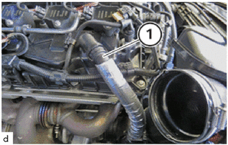
Unlock and loosen ventilation hose (1).
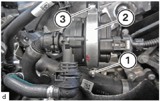
Loosen nut (1).
Guide out and remove No. 2 electric engine water pump bracket sub-assembly (2) from holder (3).
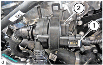
Unlock plug connection (1) and disconnect.
Guide out electric water pump assembly (2) and place it aside.
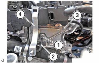
Loosen nut (1).
Feed out No. 2 engine wire (2) and set it aside.
Loosen stud bolt.
Loosen bolt (3).
Guide out and remove No. 1 electric water pump bracket sub-assembly (4).
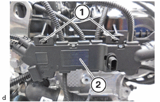
Unlock the locks (1).
Guide out the engine wiring harness for No. 2 engine wire (2) and place it aside.
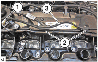
Unlock plug connection (1) and disconnect.
Loosen clamps (2).
Guide out the engine wiring harness for No. 2 engine wire (2) and place it aside.
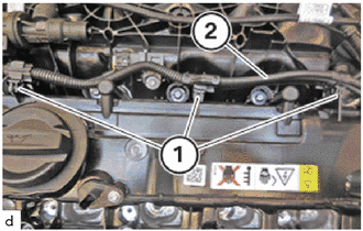
Loosen clamps (1).
Guide out the engine wiring harness for engine wire (2) and place it aside.
Unlock plug connection (1) and disconnect.
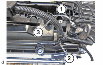
Loosen clamp (2).
Guide out the engine wiring harness for No. 2 engine wire (3) and place it aside.
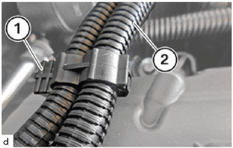
Loosen clamp (1).
Thread out the wiring harness section (2) for the injectors and ignition coils and set it aside.
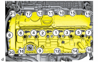
Loosen all E10 bolts in sequence (21) to (1).
Feed out and remove the cylinder head cover sub-assembly.
16.SET NO. 1 CYLINDER TO TDC (COMPRESSION)
13540
17.REMOVE NO. 1 CHAIN TENSIONER ASSEMBLY
135A0
18.LOOSEN INTAKE CAMSHAFT TIMING GEAR BOLT ASSEMBLY
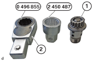
To release the intake camshaft timing gear bolt assembly (1) use the reversible ratchet (2) from the special tool 0 496855 with the special tool 2 450 487 .
- SST
- 09200-WA470
09200-WA800
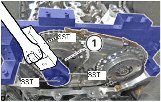
Release the intake camshaft timing gear bolt assembly of the intake camshaft adjuster (1) with the special tool 2 450 487.
- SST
- 09200-WA470
09200-WA800
09900-WA280
135A0A
19.LOOSEN EXHAUST CAMSHAFT TIMING GEAR BOLT ASSEMBLY
To release the exhaust camshaft timing gear bolt assembly (1) use the reversible ratchet (2) from the special tool 0 496855 with the special tool 2 450 487 .
- SST
- 09200-WA470
09200-WA800
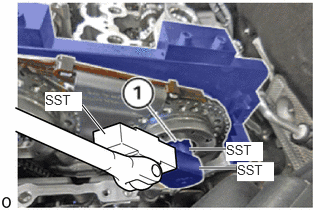
Release the exhaust camshaft timing gear bolt assembly of the exhaust camshaft adjuster (1) with the special tool 2 450 487.
- SST
- 09200-WA470
09200-WA800
09900-WA280
135A0
20.REMOVE INTAKE CAMSHAFT TIMING GEAR BOLT ASSEMBLY
- HINT:
-
The figure shows the rear side of the engine.
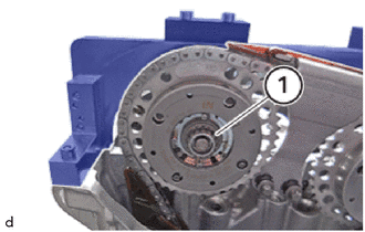
Guide out and remove the intake camshaft timing gear bolt assembly (1) of the intake adjuster.
135A0A
21.REMOVE EXHAUST CAMSHAFT TIMING GEAR BOLT ASSEMBLY
- HINT:
-
The figure shows the rear side of the engine.
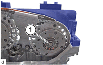
Guide out and remove the exhaust camshaft timing gear bolt assembly (1) of the exhaust camshaft adjuster.