B58 ENGINE MECHANICAL CRANKSHAFT DISASSEMBLY
PROCEDURE

 1.REMOVE ENGINE ASSEMBLY
2.REMOVE SPARK PLUG
17882
3.REMOVE NO. 2 AIR CLEANER HOSE
12101A
4.REMOVE OIL PAN DRAIN PLUG
12101A
5.INSTALL OIL PAN DRAIN PLUG
23801P
6.REMOVE NO. 1 FUEL PIPE SUB-ASSEMBLY
23100X
7.REMOVE FUEL (ENGINE ROOM SIDE) PUMP ASSEMBLY
23250
8.REMOVE FUEL INJECTOR ASSEMBLY (for Front Side)
23250
9.REMOVE FUEL INJECTOR ASSEMBLY (for Rear Side)
15370J
10.REMOVE CAM TIMING OIL CONTROL SOLENOID ASSEMBLY
11201
11.REMOVE CYLINDER HEAD COVER SUB-ASSEMBLY
17111
12.REMOVE INTAKE MANIFOLD
15474
13.REMOVE OUTLET TURBO OIL PIPE
17293
14.REMOVE TURBOCHARGER STAY
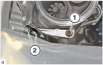
Loosen T45 bolt (1).
Release T45 bolts (2) and remove the turbocharger stay.
15.SET NO. 1 CYLINDER TO TDC (COMPRESSION)
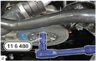
Turn the engine with the special tool 0 493 380 (11 6 480) to the TDC firing position of cylinder 1.
- SST
- 09200-WA190
- NOTICE:
- ·
Damage to the engine.
The engine may be damaged if it is manually rotated in the wrong direction.
-Always rotate the engine in the correct direction of rotation by hand: a) Clockwise, facing the crankshaft pulley assembly or b) Counter-clockwise, facing the timing chain. (b) only applies when the chain sub-assembly is installed.
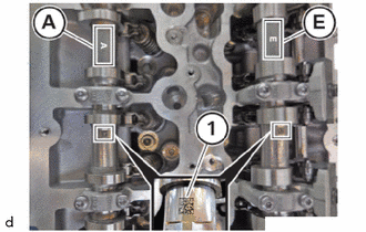
Make sure that the marks (1) on the intake camshaft sub-assembly (E) and the exhaust camshaft sub-assembly (A) are legible from above.
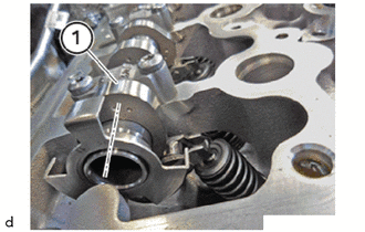
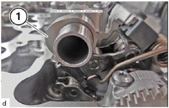
Ensure that the cam (1) on the exhaust camshaft sub-assembly on cylinder 1 points to the inside right at a slight angle.
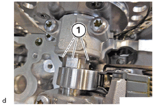
Ensure that the cam (1) on the intake camshaft sub-assembly on cylinder 1 points to the inside left at an angle.
Ensure that the flattened areas (1) on the intake camshaft sub-assembly and the exhaust camshaft sub-assembly point upwards.
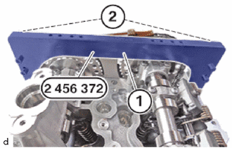
Position the basic carrier (1) from the set of special tools 2 456 372 on the cylinder head sub-assembly.
- SST
- 09200-WA700
Tighten the bolts (2) from the set of special tools 2 456 372 .
- SST
- 09200-WA700
- Torque:
- 8.0 N*m (82 kgf*cm, 71 in.*lbf)
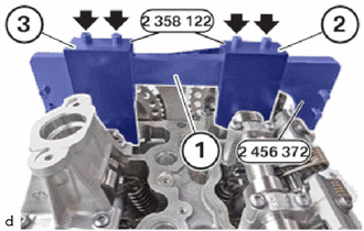
Position the test gauge (2) from the set of special tools 2 358 122 between the intake camshaft sub-assembly and the basic carrier (1) from the set of special tools 2 456 372 .
- SST
- 09200-WA380
09200-WA700
Position the test gauge (3) from the set of special tools 2 358 122 between the exhaust camshaft sub-assembly and the basic carrier (1) from the set of special tools 2 456 372 .
- SST
- 09200-WA380
09200-WA700
Tighten bolts (arrows).
- Torque:
- 8.0 N*m (82 kgf*cm, 71 in.*lbf)
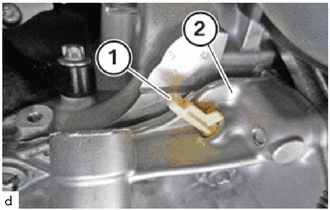
Guide out and remove sealing cap (1) on oil pan sub-assembly (2).
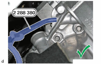
Position the special tool 2 288 380 correctly in the dowel hole .
- SST
- 09200-WA570
The engine is in the TDC firing position of cylinder 1.
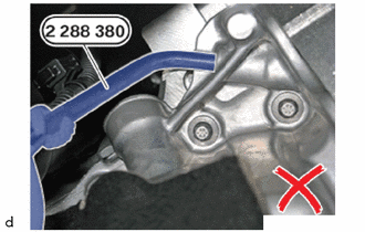
Make sure that the special tool 2 288 380 is not positioned incorrectly.
- SST
- 09200-WA570
The TDC firing position of cylinder 1 was not reached.
13540
16.REMOVE NO. 1 CHAIN TENSIONER ASSEMBLY
135A0
17.LOOSEN INTAKE CAMSHAFT TIMING GEAR BOLT ASSEMBLY
135A0A
18.LOOSEN EXHAUST CAMSHAFT TIMING GEAR BOLT ASSEMBLY
135A0
19.REMOVE INTAKE CAMSHAFT TIMING GEAR BOLT ASSEMBLY
135A0A
20.REMOVE EXHAUST CAMSHAFT TIMING GEAR BOLT ASSEMBLY
13050
21.REMOVE CAMSHAFT TIMING GEAR ASSEMBLY
13070A
22.REMOVE CAMSHAFT TIMING EXHAUST GEAR ASSEMBLY
23.REMOVE SST
11101
24.REMOVE CYLINDER HEAD SUB-ASSEMBLY
11115
25.REMOVE CYLINDER HEAD GASKET
13470
26.REMOVE CRANKSHAFT PULLEY ASSEMBLY
27.REMOVE DRIVE PLATE AND RING GEAR SUB-ASSEMBLY
12101
28.REMOVE OIL PAN SUB-ASSEMBLY
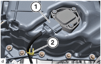
Unlock and loosen connector (1).
Loosen clamp (2).
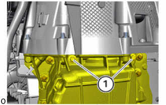
Loosen E10 bolts (1).
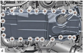
Unscrew all of the E10 bolts (marks).
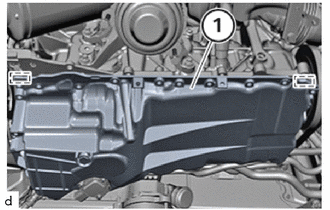
Release the oil pan sub-assembly (1) in the marked areas.
- HINT:
-
Increased force may be necessary during disassembly because the component is bonded with seal packing.
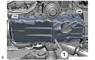
Release the oil pan sub-assembly (1) in the marked areas.
- HINT:
-
Increased force may be necessary during disassembly because the component is bonded with seal packing.
Guide out oil pan sub-assembly (1) toward the bottom and remove.
15100
29.REMOVE OIL PUMP ASSEMBLY
12121
30.REMOVE NO. 1 OIL PAN BAFFLE PLATE
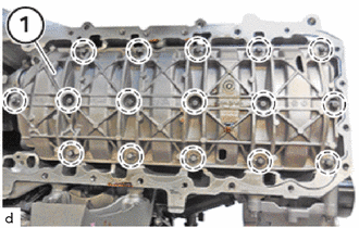
Unscrew all E10 bolts (markings).
Guide out and remove the No. 1 oil pan baffle plate (1).
13201
31.REMOVE CONNECTING ROD SUB-ASSEMBLY
11321
32.REMOVE TIMING GEAR CASE
33.REMOVE TIMING CHAIN COVER OIL SEAL
13506
34.REMOVE CHAIN SUB-ASSEMBLY
13507A
35.REMOVE OIL PUMP DRIVE CHAIN SUB-ASSEMBLY
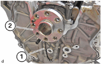
Guide out and remove oil pump drive chain sub-assembly (1) from crankshaft (2).
13411
36.REMOVE CRANKSHAFT
- NOTICE:
- ·
Engine damage may result from incorrectly installing crankshaft bearings and crankshaft bearing caps.
-Always install all crankshaft bearings and crankshaft bearing caps in the same position from which they were removed.
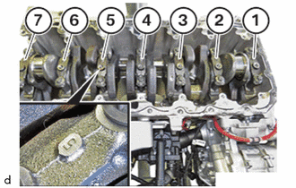
Observe the assignment and numbering (1) to (7) of the crankshaft bearing caps.
(1) = Engine, front (vibration damper)
(7) = Clutch side
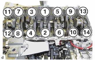
Loosen E14 bolts in the order (14) to (1).
- HINT:
-
The crankshaft bearing cap, crankshaft bearing are aligned with each other.
-
Always install the crankshaft bearing cap, crankshaft bearing in the cylinder from which they were removed.
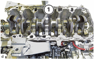
Remove the crankshaft (1).
- CAUTION:
- ·
Heavy component.
Heavy components can lead to injury or damage.
-Remove and install heavy components with the aid of another person/other persons.
11711
37.REMOVE CRANKSHAFT BEARING
- NOTICE:
- ·
Engine damage may result from incorrectly installing crankshaft bearings and crankshaft bearing caps.
-Always install all crankshaft bearings and crankshaft bearing caps in the same position from which they were removed.
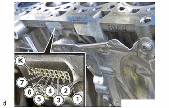
Enter the code letter on the crankcase in the table.
K = Clutch side
The position numbers (7) to (1) describe the bearing seats 7 to 1. The identification number is always located on the crankshaft bearing caps.
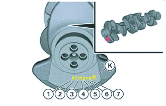
Enter the identification numbers on the crankshaft in the table.
K = Clutch side
The position numbers (1) to (7) describe the bearing seats 1 to 7. The identification number is always located on the crankshaft bearing
Enter the code letters of the crankcase and the identification numbers of the crankshaft.
| Code letter on the crankcase | Key performance indicator on the crankshaft | |
| Bearing seat 1 | ||
| Bearing seat 2 | ||
| Bearing seat 3 | ||
| Bearing seat 4 | ||
| Bearing seat 5 | ||
| Bearing seat 6 | ||
| Bearing seat 7 |
Use the table below to determine the number of the crankshaft bearings.
- HINT:
- ·
Click PDF button.
·The following illustration is an example.
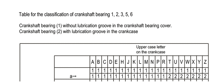
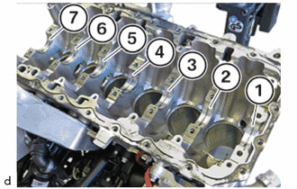
Remove the crankshaft bearings with lubricating groove (1) to (3) and (5) to (7) from the crankcase.
Remove the upper crankshaft thrust washer with lubricating groove (4) fromthe crankcase.
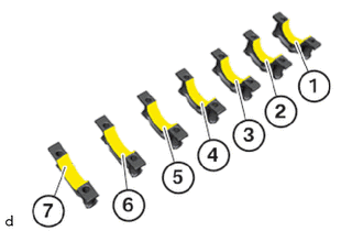
Remove the crankshaft bearings (1) to (3) and (5) to (7) from the crankshaft bearing cap.
Remove the lower crankshaft thrust washer (4) from the crankshaft bearingcap.