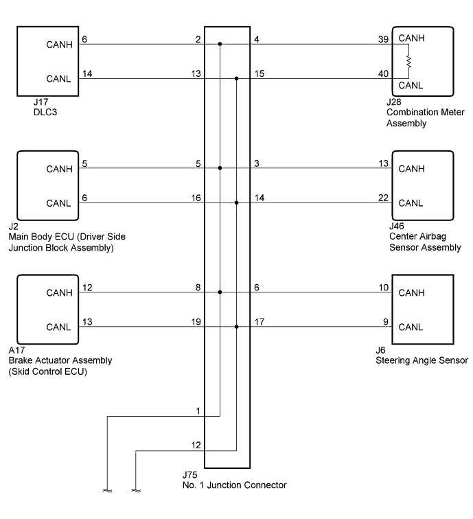
CAN COMMUNICATION SYSTEM > Open in One Side of CAN Branch Line |
| Symptom | Trouble Area |
| 2 or more ECUs and/or sensors do not appear on the Techstream "Bus Check" screen. |
|
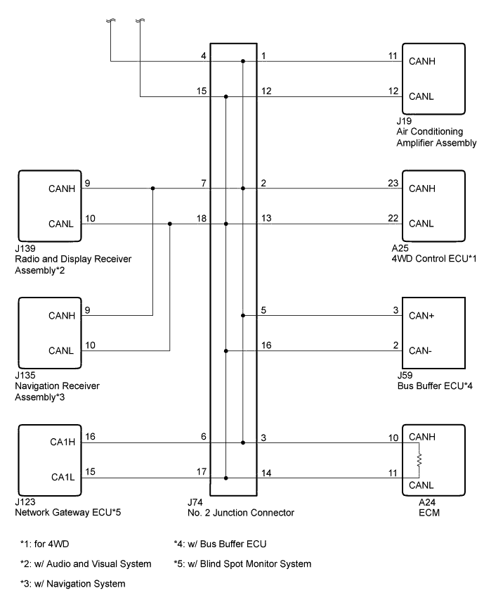
| 1.CHECK FOR OPEN IN ONE SIDE OF CAN BRANCH WIRE (CENTER AIRBAG SENSOR ASSEMBLY) |
Disconnect the J46 center airbag sensor assembly connector.
Select "Bus Check" on the Techstream (Click here).
| Result | Proceed to |
| "Airbag" is not displayed on the Techstream | A |
| Several ECUs and sensors in addition to "Airbag" are displayed on the Techstream | B |
|
| ||||
| A | |
 |
| 2.CHECK FOR OPEN IN ONE SIDE OF CAN BRANCH WIRE (CENTER AIRBAG SENSOR ASSEMBLY CAN BRANCH WIRE) |
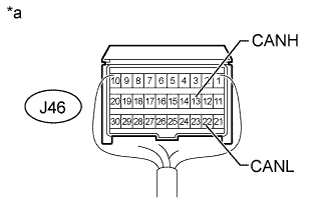 |
Disconnect the cable from the negative (-) battery terminal before measuring the resistances of the CAN main wire and the CAN branch wire.
Measure the resistance according to the value(s) in the table below.
| Tester Connection | Switch Condition | Specified Condition |
| J46-13 (CANH) - J46-22 (CANL) | Ignition switch off | 54 to 69 Ω |
| *a | Rear view of wire harness connector (to Center Airbag Sensor Assembly) |
| Result | Proceed to |
| OK (for Column Shift Type) | A |
| OK (for Floor Shift Type) | B |
| NG | C |
|
| ||||
|
| ||||
| A | ||
 | ||
| ||
| 3.CHECK FOR OPEN IN ONE SIDE OF CAN BRANCH WIRE (MAIN BODY ECU) |
Disconnect the J2 main body ECU (driver side junction block assembly) connector.
Select "Bus Check" on the Techstream (Click here).
| Result | Proceed to |
| "Main Body" is not displayed on the Techstream | A |
| Several ECUs and sensors in addition to "Main Body" are displayed on the Techstream | B |
|
| ||||
| A | |
|
| 4.CHECK FOR OPEN IN ONE SIDE OF CAN BRANCH WIRE (MAIN BODY ECU CAN BRANCH WIRE) |
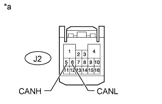 |
Disconnect the cable from the negative (-) battery terminal before measuring the resistances of the CAN main wire and the CAN branch wire.
Measure the resistance according to the value(s) in the table below.
| Tester Connection | Switch Condition | Specified Condition |
| J2-5 (CANH) - J2-6 (CANL) | Ignition switch off | 54 to 69 Ω |
| *a | Front view of wire harness connector (to Main Body ECU [Driver Side Junction Block Assembly]) |
|
| ||||
| OK | ||
| ||
| ||
| 5.CHECK FOR OPEN IN ONE SIDE OF CAN BRANCH WIRE (STEERING ANGLE SENSOR) |
Disconnect the J6 steering angle sensor connector.
Select "Bus Check" on the Techstream (Click here).
| Result | Proceed to |
| "Spiral cable (Steering Angle Sensor)" is not displayed on the Techstream | A |
| Several ECUs and sensors in addition to "Spiral cable (Steering Angle Sensor)" are displayed on the Techstream | B |
|
| ||||
| A | |
|
| 6.CHECK FOR OPEN IN ONE SIDE OF CAN BRANCH WIRE (STEERING ANGLE SENSOR CAN BRANCH WIRE) |
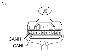 |
Disconnect the cable from the negative (-) battery terminal before measuring the resistances of the CAN main wire and the CAN branch wire.
Measure the resistance according to the value(s) in the table below.
| Tester Connection | Switch Condition | Specified Condition |
| J6-10 (CANH) - J6-9 (CANL) | Ignition switch off | 54 to 69 Ω |
| *a | Rear view of wire harness connector (to Steering Angle Sensor) |
|
| ||||
| OK | ||
| ||
| ||
| 7.CHECK FOR OPEN IN ONE SIDE OF CAN BRANCH WIRE (SKID CONTROL ECU) |
Disconnect the A17 brake actuator assembly (skid control ECU) connector.
Select "Bus Check" on the Techstream (Click here).
| Result | Proceed to |
| "Skid Control (ABS/VSC/TRAC)" is not displayed on the Techstream | A |
| Several ECUs and sensors in addition to ""Skid Control (ABS/VSC/TRAC)" are displayed on the Techstream | B |
|
| ||||
| A | |
|
| 8.CHECK FOR OPEN IN ONE SIDE OF CAN BRANCH WIRE (SKID CONTROL ECU CAN BRANCH WIRE) |
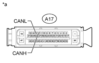 |
Disconnect the cable from the negative (-) battery terminal before measuring the resistances of the CAN main wire and the CAN branch wire.
Measure the resistance according to the value(s) in the table below.
| Tester Connection | Switch Condition | Specified Condition |
| A17-12 (CANH) - A17-13 (CANL) | Ignition switch off | 54 to 69 Ω |
| *a | Front view of wire harness connector (to Brake Actuator Assembly [Skid Control ECU]) |
|
| ||||
| OK | ||
| ||
| ||
| 9.CHECK FOR OPEN IN ONE SIDE OF CAN BRANCH WIRE (4WD CONTROL ECU) |
Disconnect the A25 4WD control ECU connector.
Select "Bus Check" on the Techstream (Click here).
| Result | Proceed to |
| "Four Wheel Drive Control" is not displayed on the Techstream | A |
| Several ECUs and sensors in addition to "Four Wheel Drive Control" are displayed on the Techstream | B |
|
| ||||
| A | |
|
| 10.CHECK FOR OPEN IN ONE SIDE OF CAN BRANCH WIRE (4WD CONTROL ECU CAN BRANCH WIRE) |
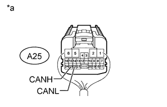 |
Disconnect the cable from the negative (-) battery terminal before measuring the resistances of the CAN main wire and the CAN branch wire.
Measure the resistance according to the value(s) in the table below.
| Tester Connection | Switch Condition | Specified Condition |
| A25-23 (CANH) - A25-22 (CANL) | Ignition switch off | 54 to 69 Ω |
| *a | Rear view of wire harness connector (to 4WD Control ECU) |
|
| ||||
| OK | ||
| ||
| ||
| 11.CHECK FOR OPEN IN ONE SIDE OF CAN BRANCH WIRE (BUS BUFFER ECU) |
Disconnect the J59 bus buffer ECU connector.
Select "Bus Check" on the Techstream (Click here).
| Result | Proceed to |
| "Accessory Gateway" is not displayed on the Techstream | A |
| Several ECUs and sensors in addition to "Accessory Gateway" are displayed on the Techstream | B |
|
| ||||
| A | |
|
| 12.CHECK FOR OPEN IN ONE SIDE OF CAN BRANCH WIRE (BUS BUFFER ECU CAN BRANCH WIRE) |
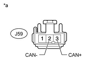 |
Disconnect the cable from the negative (-) battery terminal before measuring the resistances of the CAN main wire and the CAN branch wire.
Measure the resistance according to the value(s) in the table below.
| Tester Connection | Switch Condition | Specified Condition |
| J59-3 (CAN+) - J59-2 (CAN-) | Ignition switch off | 54 to 69 Ω |
| *a | Front view of wire harness connector (to Bus Buffer ECU) |
|
| ||||
| OK | ||
| ||
| ||
| 13.CHECK FOR OPEN IN ONE SIDE OF CAN BRANCH WIRE (NETWORK GATEWAY ECU) |
Disconnect the J123 network gateway ECU connector.
Select "Bus Check" on the Techstream (Click here).
| Result | Proceed to |
| "CAN Gateway" is not displayed on the Techstream | A |
| Several ECUs and sensors in addition to "CAN Gateway" are displayed on the Techstream | B |
|
| ||||
| A | |
|
| 14.CHECK FOR OPEN IN ONE SIDE OF CAN BRANCH WIRE (NETWORK GATEWAY ECU CAN BRANCH WIRE) |
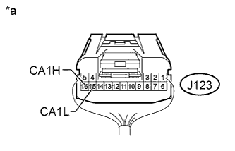 |
Disconnect the cable from the negative (-) battery terminal before measuring the resistances of the CAN main wire and the CAN branch wire.
Measure the resistance according to the value(s) in the table below.
| Tester Connection | Switch Condition | Specified Condition |
| J123-16 (CA1H) - J123-15 (CA1L) | Ignition switch off | 54 to 69 Ω |
| *a | Rear view of wire harness connector (to Network Gateway ECU) |
|
| ||||
| OK | ||
| ||
| ||
| 15.CHECK FOR OPEN IN ONE SIDE OF CAN BRANCH WIRE (AIR CONDITIONING AMPLIFIER ASSEMBLY) |
Disconnect the J19 air conditioning amplifier assembly connector.
Select "Bus Check" on the Techstream (Click here).
| Result | Proceed to |
| "Air Conditioning Amplifier" is not displayed on the Techstream | A |
| Several ECUs and sensors in addition to "Air Conditioning Amplifier" are displayed on the Techstream (w/ Audio and Visual System) | B |
| Several ECUs and sensors in addition to "Air Conditioning Amplifier" are displayed on the Techstream (w/ Navigation System) | C |
|
| ||||
|
| ||||
| A | |
|
| 16.CHECK FOR OPEN IN ONE SIDE OF CAN BRANCH WIRE (AIR CONDITIONING AMPLIFIER ASSEMBLY CAN BRANCH WIRE) |
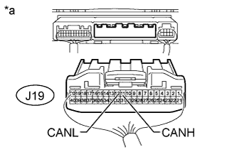 |
Disconnect the cable from the negative (-) battery terminal before measuring the resistances of the CAN main wire and the CAN branch wire.
Disconnect the J19 air conditioning amplifier assembly connector.
Measure the resistance according to the value(s) in the table below.
| Tester Connection | Switch Condition | Specified Condition |
| J19-11 (CANH) - J19-12 (CANL) | Ignition switch off | 54 to 69 Ω |
| *a | Rear view of wire harness connector (to Air Conditioning Amplifier Assembly) |
|
| ||||
| OK | ||
| ||
| ||
| 17.CHECK FOR OPEN IN ONE SIDE OF CAN BRANCH WIRE (RADIO AND DISPLAY RECEIVER ASSEMBLY CAN BRANCH WIRE) |
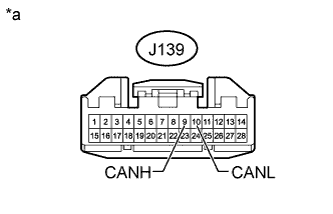 |
Disconnect the cable from the negative (-) battery terminal before measuring the resistances of the CAN main wire and the CAN branch wire.
Disconnect the J139 radio and display receiver assembly connector.
Measure the resistance according to the value(s) in the table below.
| Tester Connection | Switch Condition | Specified Condition |
| J139-9 (CANH) - J139-10 (CANL) | Ignition switch off | 54 to 69 Ω |
| *a | Front view of wire harness connector (to Radio and Display Receiver Assembly) |
| Result | Proceed to |
| OK (for Column Shift Type) | A |
| OK (for Floor Shift Type) | B |
| NG | C |
|
| ||||
|
| ||||
| A | ||
| ||
| ||
| 18.CHECK FOR OPEN IN ONE SIDE OF CAN BRANCH WIRE (NAVIGATION RECEIVER ASSEMBLY CAN BRANCH WIRE) |
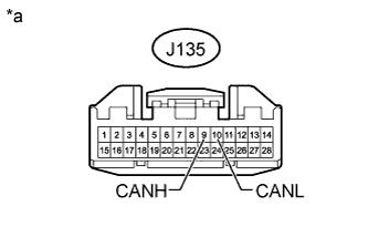 |
Disconnect the cable from the negative (-) battery terminal before measuring the resistances of the CAN main wire and the CAN branch wire.
Disconnect the J135 navigation receiver assembly connector.
Measure the resistance according to the value(s) in the table below.
| Tester Connection | Switch Condition | Specified Condition |
| J135-9 (CANH) - J135-10 (CANL) | Ignition switch off | 54 to 69 Ω |
| *a | Front view of wire harness connector (to Navigation Receiver Assembly) |
| Result | Proceed to |
| OK (for Column Shift Type) | A |
| OK (for Floor Shift Type) | B |
| NG | C |
|
| ||||
|
| ||||
| A | ||
| ||
| ||

