3UR-FE STARTING STARTER INSTALLATION
PROCEDURE

 28100
1.INSTALL STARTER ASSEMBLY
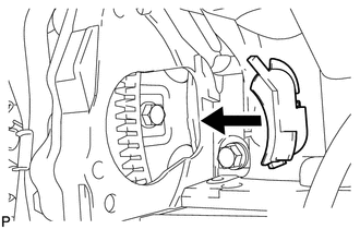
Install the flywheel housing side cover.
Install the starter with the 2 bolts.
- Torque:
- 37 N*m (377 kgf*cm, 27 ft.*lbf)
Install the starter wire with the nut.
- Torque:
- 9.8 N*m (100 kgf*cm, 87 in.*lbf)
Connect the starter connector.
Attach the 2 wire harness clamps.
28192
2.INSTALL STARTER COVER
Install the starter cover with the 3 bolts.
- Torque:
- 12 N*m (117 kgf*cm, 8 ft.*lbf)
17104
3.INSTALL EXHAUST MANIFOLD SUB-ASSEMBLY RH
17167
4.INSTALL NO. 1 EXHAUST MANIFOLD HEAT INSULATOR
17410
5.INSTALL FRONT EXHAUST PIPE ASSEMBLY
Install a new gasket and the exhaust pipe to the exhaust manifold RH with 3 new nuts.
- Torque:
- 54 N*m (554 kgf*cm, 40 ft.*lbf)
Install a new gasket and the exhaust pipe to the center exhaust pipe with the 2 bolts.
- Torque:
- 48 N*m (489 kgf*cm, 35 ft.*lbf)
Connect the air fuel ratio sensor connector.
Connect the heated oxygen sensor connector and attach the 2 clamps.
11452
6.INSTALL ENGINE OIL LEVEL DIPSTICK GUIDE
Apply a light coat of engine oil to a new O-ring.
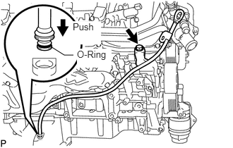
Install the O-ring to the guide.
Install the dipstick guide with the bolt.
- Torque:
- 10 N*m (102 kgf*cm, 7 ft.*lbf)
Install the dipstick.
27020
7.INSTALL GENERATOR ASSEMBLY
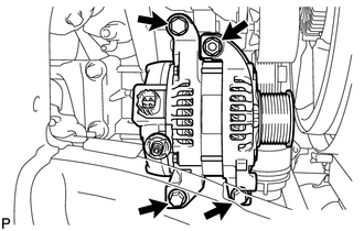
Install the generator with the 3 bolts and nut.
- Torque:
- 43 N*m (439 kgf*cm, 32 ft.*lbf)
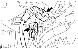
Connect the generator connector.
Connect the generator wire with the nut.
- Torque:
- 9.8 N*m (100 kgf*cm, 87 in.*lbf)
Install the terminal cap.
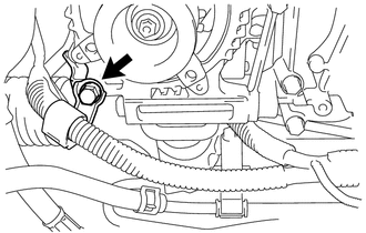
Install the harness bracket to the generator with the bolt.
- Torque:
- 31 N*m (316 kgf*cm, 23 ft.*lbf)
44320
8.CONNECT VANE PUMP ASSEMBLY
- HINT:
-
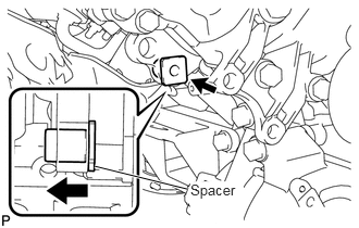 1.75,1.844 1.688,1.844 false 1.792,1.813 0.906,1.594 true 1.823,1.74 2.333,2.135 0.51,0.396 10 true Spacer
-
Before performing the following procedures, move the spacer until the vane pump can be installed.
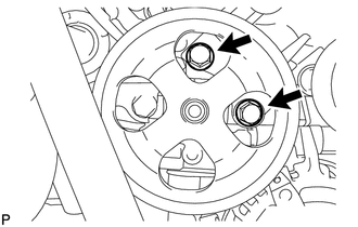
Connect the vane pump to the timing chain cover with the 2 bolts.
- Torque:
- 28 N*m (286 kgf*cm, 21 ft.*lbf)
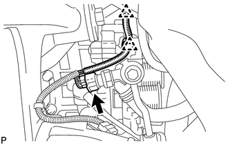
Attach the 2 clamps and connect the power steering oil pressure switch connector.
53736
9.INSTALL FRONT FENDER APRON SEAL RH
16361A
10.INSTALL FAN AND GENERATOR V BELT
17700
11.INSTALL AIR CLEANER ASSEMBLY
17880
12.INSTALL AIR CLEANER HOSE ASSEMBLY
11209
13.INSTALL V-BANK COVER SUB-ASSEMBLY
51441
14.INSTALL NO. 1 ENGINE UNDER COVER
15.CONNECT CABLE TO NEGATIVE BATTERY TERMINAL