2NZ-FE LUBRICATION OIL PUMP INSTALLATION
PROCEDURE

 15100
1.INSTALL OIL PUMP ASSEMBLY
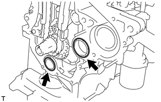
Install 2 new O-rings onto the 2 locations as shown in the illustration.
Apply seal packing to the oil pump assembly, cylinder head and cylinder block as shown in the illustration.
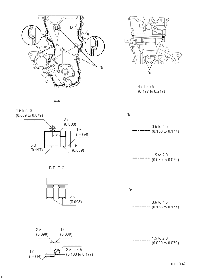
| *a | Seal Packing | *b | Seal Width (Other Part) |
| *c | Seal Width (Water Pump Part) | - | - |
- Seal packing:
Water pump part Toyota Genuine Seal Packing 1282B, Three Bond 1282B or equivalent
Other part Toyota Genuine Seal Packing Black, Three Bond 1207B or equivalent
- NOTICE:
- ·
Remove any oil from the contact surfaces.
·Install the oil pump assembly within 3 minutes and tighten the bolts and nut within 15 minutes of applying seal packing.
·Do not expose the seal to engine oil for at least 2 hours after the installation.
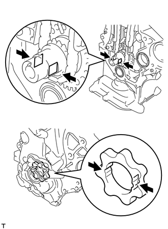
Align the keyway of the oil pump rotor with the rectangular portion of the crankshaft, and slide the oil pump into place.
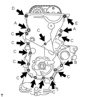
Install the oil pump assembly with the 15 bolts and the nut. Tighten the bolts and nut uniformly in several steps.
- Torque:
- bolt A : 32 N*m (326 kgf*cm, 24 ft.*lbf)
- bolt B : 12 N*m (122 kgf*cm, 9 ft.*lbf)
- bolt C : 12 N*m (122 kgf*cm, 9 ft.*lbf)
- nut D : 24 N*m (245 kgf*cm, 18 ft.*lbf)
- bolt E : 24 N*m (245 kgf*cm, 18 ft.*lbf)
- NOTICE:
-
After installing the oil pump assembly, install the mounting bracket and water pump within 15 minutes.
- HINT:
-
Each bolt length is as follows.
-
A: 30 mm (1.181 in.)
-
B: 35 mm (1.378 in.)
-
C: 20 mm (0.787 in.)
-
E: 14 to 20 mm (0.551 to 0.787 in.), Double ended bolt
12315A
2.INSTALL TRANSVERSE ENGINE ENGINE MOUNTING BRACKET
Install the transverse engine engine mounting bracket with the 4 bolts.
- Torque:
- 55 N*m (561 kgf*cm, 41 ft.*lbf)
16100
3.INSTALL WATER PUMP ASSEMBLY
16173
4.INSTALL WATER PUMP PULLEY
11101J
5.INSTALL CAMSHAFT TIMING OIL CONTROL VALVE ASSEMBLY
15100Q
6.INSTALL CRANKSHAFT POSITION SENSOR
13407
7.INSTALL CRANKSHAFT DAMPER SUB-ASSEMBLY
Align the pin hole of the crankshaft damper with the pin and install the crankshaft damper sub-assembly.
Provisionally install the bolt.
Using 2 SST, tighten the bolt while holding the crankshaft damper sub-assembly.
- SST
- 09213-14010 (91651-60865)
09330-00021
- Torque:
- 128 N*m (1305 kgf*cm, 95 ft.*lbf)
- NOTICE:
-
Check the SST installation positions when installing them, to avoid the SST fixing bolts from coming into contact with the oil pump assembly.
12305
8.INSTALL ENGINE MOUNTING INSULATOR SUB-ASSEMBLY RH
Install the engine mounting insulator sub-assembly RH with the 4 bolts and 2 nuts.
- Torque:
- 52 N*m (530 kgf*cm, 38 ft.*lbf)
11201
9.INSTALL CYLINDER HEAD COVER SUB-ASSEMBLY
23820
10.INSTALL FUEL VAPOR FEED HOSE ASSEMBLY
12261
11.INSTALL VENTILATION HOSE
19500D
12.INSTALL NO. 1 IGNITION COIL
27020
13.INSTALL GENERATOR ASSEMBLY
14.CONNECT CABLE TO NEGATIVE BATTERY TERMINAL
- Torque:
- 5.4 N*m (55 kgf*cm, 48 in.*lbf)
15.ADD ENGINE OIL
16.ADD COOLANT
17.INSPECT ENGINE OIL LEVEL
18.INSPECT FOR OIL LEAK
19.INSPECT FOR COOLANT LEAK
51442C
20.INSTALL ENGINE UNDER COVER LH (for Plastic Type)
- Torque:
- 5.0 N*m (51 kgf*cm, 44 in.*lbf)
51441C
21.INSTALL ENGINE UNDER COVER RH (for Plastic Type)
- Torque:
- 5.0 N*m (51 kgf*cm, 44 in.*lbf)
51405A
22.INSTALL NO. 1 ENGINE UNDER COVER SUB-ASSEMBLY (for Metal Type)
- Torque:
- 18 N*m (184 kgf*cm, 13 ft.*lbf)
23.INSTALL FRONT WHEEL RH
- Torque:
- 103 N*m (1050 kgf*cm, 76 ft.*lbf)