1NZ-FE ENGINE MECHANICAL ENGINE UNIT DISASSEMBLY
PROCEDURE

 19100P
1.REMOVE SPARK PLUG
16321
2.REMOVE WATER INLET
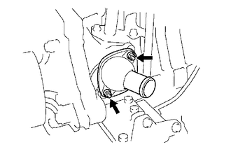
Remove the 2 nuts and water inlet from the cylinder block sub-assembly.
16331A
3.REMOVE THERMOSTAT
12108
4.REMOVE OIL FILLER CAP SUB-ASSEMBLY
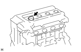
Remove the oil filler cap sub-assembly from the cylinder head cover sub-assembly.
12108A
5.REMOVE OIL FILLER CAP GASKET
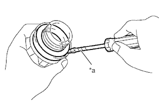
| *a | Protective Tape |
Using a screwdriver with its tip wrapped in protective tape, remove the oil filler cap gasket from the oil filler cap sub-assembly.
15100Q
6.REMOVE CRANKSHAFT POSITION SENSOR
12204
7.REMOVE VENTILATION VALVE SUB-ASSEMBLY
11201
8.REMOVE CYLINDER HEAD COVER SUB-ASSEMBLY
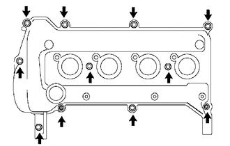
Remove the 9 bolts, 2 nuts, 2 cylinder head cover seal washers and cylinder head cover sub-assembly from the cylinder head sub-assembly.
Remove the cylinder head cover gasket from the cylinder head cover sub-assembly.
23807
9.REMOVE FUEL DELIVERY PIPE SUB-ASSEMBLY
23891
10.REMOVE FUEL DELIVERY SPACER
23291
11.REMOVE INJECTOR VIBRATION INSULATOR
23250
12.REMOVE FUEL INJECTOR ASSEMBLY
11101J
13.REMOVE CAMSHAFT TIMING OIL CONTROL VALVE ASSEMBLY
11452
14.REMOVE OIL LEVEL DIPSTICK GUIDE
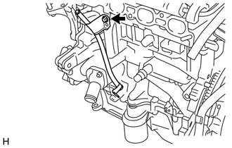
Remove the bolt and oil level dipstick guide from the cylinder block sub-assembly.
Remove the O-ring from the oil level dipstick guide.
16173
15.REMOVE WATER PUMP PULLEY
13407
16.REMOVE CRANKSHAFT DAMPER SUB-ASSEMBLY
12315A
17.REMOVE ENGINE MOUNTING BRACKET RH
16100
18.REMOVE ENGINE WATER PUMP ASSEMBLY
15100
19.REMOVE OIL PUMP ASSEMBLY
15100C
20.REMOVE OIL PUMP SEAL
13540
21.REMOVE NO. 1 CHAIN TENSIONER ASSEMBLY
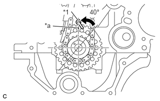
| *1 | Oil Jet |
| *a | Timing Mark (1 dot) |
- NOTICE:
- ·
Do not rotate the crankshaft with the No. 1 chain tensioner assembly removed.
·When rotating the camshaft with the chain sub-assembly removed, rotate the crankshaft counterclockwise 40° from the TDC first, and align the oil jet hole with the timing mark (1 dot). This prevents the pistons from coming into contact with the valves.
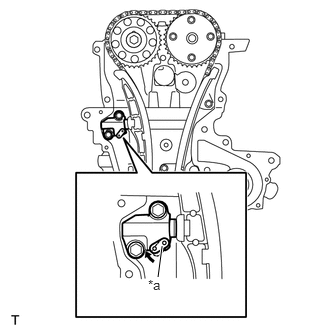
| *a | Stopper Plate |
Pull up the stopper plate and hold it with its lock released.
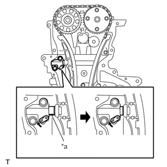
| *a | Plunger |
Unlock the plunger of the No. 1 chain tensioner assembly and push it in to the end.
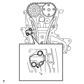
| *a | Stopper Plate |
Pull down the stopper plate with the plunger pushed to the end and lock the plunger.
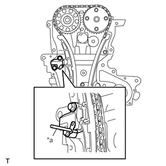
| *a | 3 mm Diameter Bar |
Insert a 3 mm (0.12 in.) diameter bar into the hole in the stopper plate and lock the plunger.
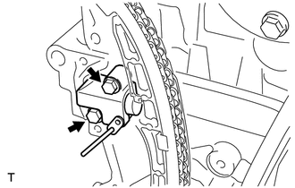
Remove the 2 bolts and No. 1 chain tensioner assembly from the cylinder block sub-assembly.
13559
22.REMOVE CHAIN TENSIONER SLIPPER
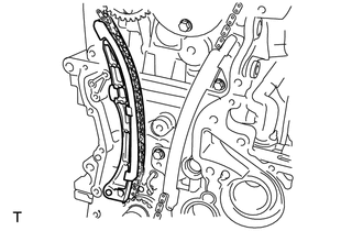
Remove the chain tensioner slipper from the cylinder block sub-assembly.
13561
23.REMOVE NO. 1 CHAIN VIBRATION DAMPER
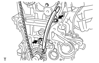
Remove the 2 bolts and No. 1 chain vibration damper from the cylinder head sub-assembly and cylinder block sub-assembly.
13506
24.REMOVE CHAIN SUB-ASSEMBLY
Remove the chain sub-assembly from the camshaft timing gear assembly, camshaft timing sprocket and crankshaft.
11101E
25.REMOVE CAMSHAFT POSITION SENSOR
13512
26.REMOVE NO. 2 CAMSHAFT
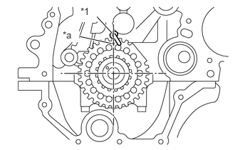
| *1 | Oil Jet |
| *a | Timing Mark (1 dot) |
- NOTICE:
-
When rotating the camshaft with the chain sub-assembly removed, rotate the crankshaft counterclockwise 40° from TDC first, and align the oil jet hole with the timing mark. This prevents the pistons from coming into contact with the valves.
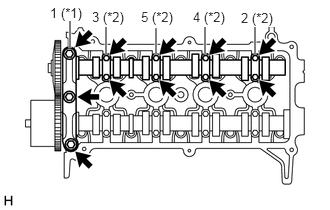
| *1 | No. 1 Camshaft Bearing Cap |
| *2 | No. 2 Camshaft Bearing Cap |
Using several steps, loosen and remove the 11 bolts uniformly in the sequence shown in the illustration, then remove the No. 1 camshaft bearing cap and 4 No. 2 camshaft bearing caps from the cylinder head sub-assembly.
- NOTICE:
-
Loosen the bolts uniformly while keeping the No. 2 camshaft level.
Remove the No. 2 camshaft from the cylinder head sub-assembly.
13523
27.REMOVE CAMSHAFT TIMING SPROCKET
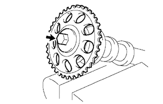
Clamp the No. 2 camshaft in a vise, and confirm that it is locked.
- NOTICE:
-
Do not damage the No. 2 camshaft.
Remove the bolt and camshaft timing sprocket from the No. 2 camshaft.
13511
28.REMOVE CAMSHAFT
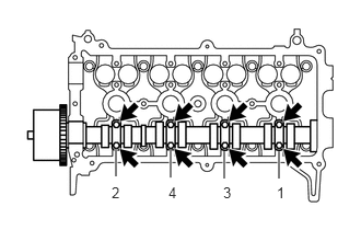
Using several steps, loosen and remove the 8 bolts uniformly in the sequence shown in the illustration, then remove the 4 No. 2 camshaft bearing caps from the cylinder head sub-assembly.
- NOTICE:
-
Loosen the bolts uniformly while keeping the camshaft level.
Remove the camshaft from the cylinder head sub-assembly.
13050
29.REMOVE CAMSHAFT TIMING GEAR ASSEMBLY
Clamp the camshaft in a vise, and confirm that it is locked.
- NOTICE:
-
Do not damage the camshaft.
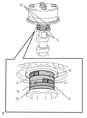
| *a | Rubber Piece |
| *b | Vinyl Tape |
| *c | Advance Side Paths |
| *d | Retard Side Paths |
| *e | Open |
| *f | Closed |
Cover the 4 oil paths of the cam journal with the vinyl tape as shown in the illustration.
- HINT:
-
One of the 2 grooves located on the cam journal is for retarding cam timing (upper) and other is for advancing cam timing (lower). Each groove has 2 oil paths. Plug one of the oil paths for each groove with a rubber piece before wrapping the cam journal with the vinyl tape.
Prick a hole in the vinyl tape covering the advance oil path and retard oil path on the opposite side from the advance oil path.
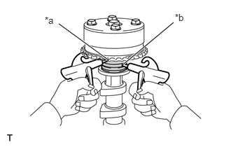
| *a | Retard Side Paths |
| *b | Advance Side Paths |
Apply compressed air of approximately 150 kPa (1.5 kgf/cm2, 22 psi) pressure into the 2 broken paths (the advance side path and retard side path).
- NOTICE:
-
Cover the paths with a piece of cloth to prevent oil splashes.
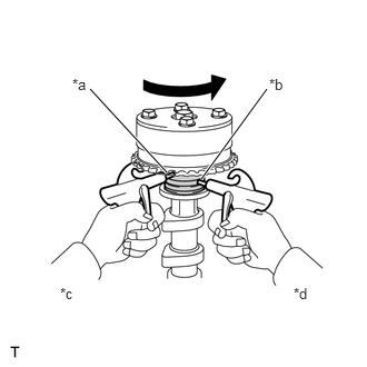
| *a | Retard Side Paths |
| *b | Advance Side Paths |
| *c | Decompress |
| *d | Hold Pressure |
Confirm that the camshaft timing gear assembly revolves in the timing advance direction when the air pressure on the timing retard path is reduced.
- HINT:
-
The lock pin is released and camshaft timing gear assembly revolves in the advance direction.
When the camshaft timing gear assembly reaches the most advanced position, release the air pressure on the timing retard side path, and then release the air pressure on the timing advance side path.
- NOTICE:
-
Camshaft timing gear assembly occasionally shifts to the retard side abruptly if the air pressure on the advance side path is released first. It often results in the breakage of the lock pin.
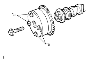
| *a | Do not remove |
Remove the bolt and camshaft timing gear assembly from the camshaft.
- NOTICE:
- ·
Do not remove the other 4 bolts.
·When reusing the camshaft timing gear assembly, unlock the lock pin inside the camshaft timing gear assembly first.
11101
30.REMOVE CYLINDER HEAD SUB-ASSEMBLY
11115
31.REMOVE CYLINDER HEAD GASKET
15601
32.REMOVE OIL FILTER SUB-ASSEMBLY
15600A
33.REMOVE OIL FILTER UNION
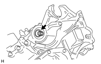
Using a 12 mm hexagon wrench, remove the oil filter union from the oil pan sub-assembly.
11401L
34.REMOVE REAR ENGINE OIL SEAL
12102A
35.REMOVE NO. 2 OIL PAN SUB-ASSEMBLY
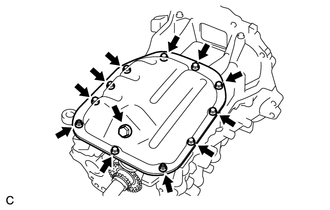
Remove the oil pan drain plug and gasket from the No. 2 oil pan sub-assembly.
Remove the 9 bolts and 2 nuts.
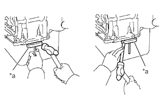
| *a | Oil Pan Seal Cutter |
Insert the blade of oil pan seal cutter between the oil pan sub-assembly and No. 2 oil pan sub-assembly, cut off the applied sealer and remove No. 2 oil pan sub-assembly from the oil pan sub-assembly.
- NOTICE:
-
Do not damage the oil pan sub-assembly or No. 2 oil pan sub-assembly.
15104
36.REMOVE OIL STRAINER SUB-ASSEMBLY
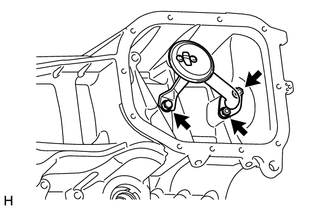
Remove the bolt, 2 nuts, oil strainer sub-assembly and oil strainer gasket from the oil pan sub-assembly.
12101
37.REMOVE OIL PAN SUB-ASSEMBLY
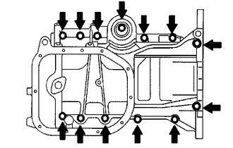
Loosen and remove the 13 bolts uniformly in several steps.
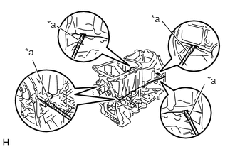
| *a | Protective Tape |
Using a screwdriver with its tip wrapped in protective tape, remove the oil pan sub-assembly by prying between the cylinder block sub-assembly and oil pan sub-assembly.
- NOTICE:
-
Be careful not to damage the contact surfaces of the oil pan sub-assembly.
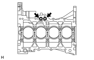
Remove the 2 O-rings from the cylinder block sub-assembly.
15104E
38.REMOVE STUD BOLT
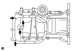
Using an E5 "TORX" socket wrench, remove the 4 stud bolts from the oil pan sub-assembly.