INTERIOR PANELS / TRIM ROOF HEADLINING(for 3 Door) INSTALLATION
PROCEDURE

 63311C
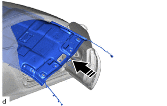
1.INSTALL ROOF HEADLINING

|
Install in this Direction |
Tilt the roof headlining diagonally and insert it into the cabin through the passenger side door.
- NOTICE:
- ·
Check that the corners of the roof headlining are not folded, twisted or otherwise deformed and that none of the mounted parts have fallen off.
·Make sure that the roof headlining does not get caught on anything as it may become bent or damaged.
·Do not damage the roof headlining or vehicle interior.
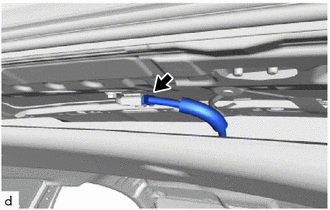
Connect the connector.
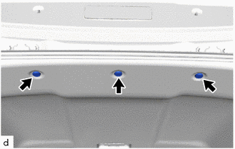
Install the 3 clips.
for Rear Pillar RH Side:
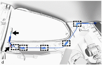
Engage the clamps.
Install the bolt.
- Torque:
- 10 N*m (102 kgf*cm, 7 ft.*lbf)
Connect the connector.
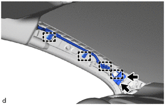
for Front Pillar LH Side:
Engage the clamps.
Connect the 2 connectors.
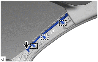
for Front Pillar RH Side:
Engage the clamps.
Connect the connector.
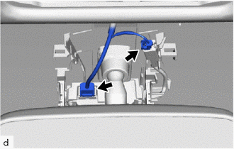
for Windshield Glass Side:
w/o Toyota Safety Sense 2:
Connect the 2 connectors.
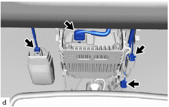
w/ Toyota Safety Sense 2:
Connect the 4 connectors.
86466D
2.INSTALL NO. 1 FORWARD RECOGNITION COVER (w/ Toyota Safety Sense 2)
86466E
3.INSTALL NO. 2 FORWARD RECOGNITION COVER (w/ Toyota Safety Sense 2)
87818
4.INSTALL INNER REAR VIEW MIRROR COVER (w/o Toyota Safety Sense 2)
89943
5.INSTALL RAIN SENSOR COVER (w/ Rain Sensor)
89732A
6.INSTALL THEFT WARNING ULTRASONIC SENSOR (w/ Intrusion Sensor)
81240J
7.INSTALL ROOM LIGHT ASSEMBLY
81260A
8.INSTALL MAP LIGHT ASSEMBLY
74612
9.INSTALL ASSIST GRIP COVER
- HINT:
-
Use the same procedure for all assist grip sub-assemblies.
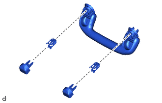
Install the 2 assist grip covers and 2 clips to the assist grip sub-assembly.
74610A
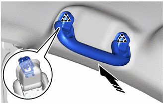
10.INSTALL ASSIST GRIP SUB-ASSEMBLY
- HINT:
-
Use the same procedures for the opposite side.
|
|
Install in this Direction |
Engage the clips to install the assist grip sub-assembly as shown in the illustration.
74348C
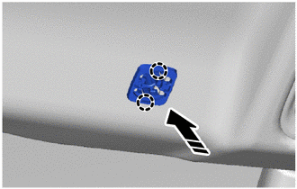
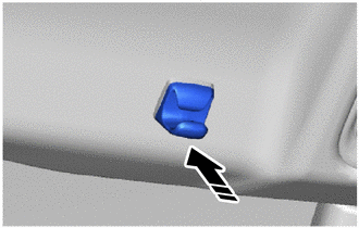
11.INSTALL VISOR HOLDER
- HINT:
-
Use the same procedures for the opposite side.
|
|
Install in this Direction |
Engage the claws to install the base as shown in the illustration.
|
|
Install in this Direction |
Install the visor holder as shown in the illustration.
74320
12.INSTALL VISOR ASSEMBLY LH
74310
13.INSTALL VISOR ASSEMBLY RH
- HINT:
-
Use the same procedure as for the LH side.
62452
14.INSTALL ROOF SIDE INNER GARNISH LH
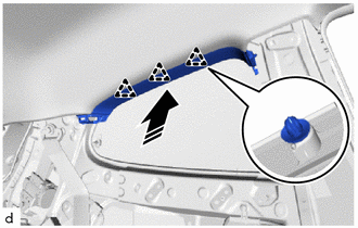
|
|
Install in this Direction |
Engage the clips to install the roof side inner garnish LH as shown in the illustration.
62451
15.INSTALL ROOF SIDE INNER GARNISH RH
- HINT:
-
Use the same procedure as for the LH side.
62472A
16.INSTALL INNER ROOF SIDE GARNISH LH
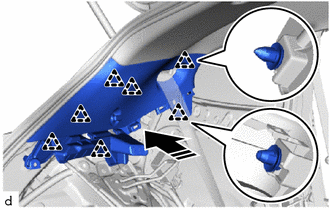
|
|
Install in this Direction |
Engage the clips to install the inner roof side garnish LH as shown in the illustration.
62471A
17.INSTALL INNER ROOF SIDE GARNISH RH
- HINT:
-
Use the same procedure as for the LH side.
73370E
18.INSTALL REAR SEAT OUTER BELT ASSEMBLY LH
73360D
19.INSTALL REAR SEAT OUTER BELT ASSEMBLY RH
- HINT:
-
Use the same procedure as for the LH side.
64740C
20.INSTALL DECK TRIM SIDE PANEL ASSEMBLY LH
Install the 3 clips and deck trim side panel assembly LH.
64730B
21.INSTALL DECK TRIM SIDE PANEL ASSEMBLY RH
- HINT:
-
Use the same procedure as for the LH side.
64716D
22.INSTALL DECK TRIM REAR COVER
Engage the clips to install the deck trim rear cover.
62412B
23.INSTALL CENTER PILLAR UPPER GARNISH LH
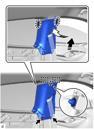
|
|
Install in this Direction (1) |

|
Install in this Direction (2) |
Engage the clip and guides to install the center pillar upper garnish LH as shown in the illustration.
Install the 2 clips.
62411B
24.INSTALL CENTER PILLAR UPPER GARNISH RH
- HINT:
-
Use the same procedure as for the LH side.
62520B
25.INSTALL QUARTER TRIM PANEL ASSEMBLY LH
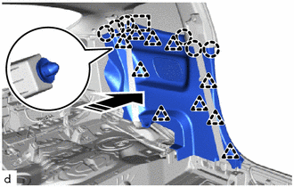
|
|
Install in this Direction |
Engage the claws, clips and guide to install the quarter trim panel assembly LH as shown in the illustration.
62510M
26.INSTALL QUARTER TRIM PANEL ASSEMBLY RH
- HINT:
-
Use the same procedure as for the LH side.
71304C
27.INSTALL REAR SEATBACK HINGE SUB-ASSEMBLY LH
Install the rear seatback hinge sub-assembly LH with the bolt.
- Torque:
- 18.1 N*m (185 kgf*cm, 13 ft.*lbf)
71303C
28.INSTALL REAR SEATBACK HINGE SUB-ASSEMBLY RH
- HINT:
-
Use the same procedure as for the LH side.
73220
29.INSTALL FRONT SEAT OUTER BELT ASSEMBLY LH
73210
30.INSTALL FRONT SEAT OUTER BELT ASSEMBLY RH
- HINT:
-
Use the same procedure as for the LH side.
73233
31.INSTALL LAP BELT OUTER ANCHOR COVER
Click hereVehicle Interior>SEAT BELT>FRONT SEAT OUTER BELT ASSEMBLY (for 3 Door)>INSTALLATION
- HINT:
-
Use the same procedures for the opposite side.
62212
32.INSTALL FRONT PILLAR GARNISH LH
62211
33.INSTALL FRONT PILLAR GARNISH RH
- HINT:
-
Use the same procedure as for the LH side.
62312B
34.INSTALL FRONT DOOR OPENING TRIM WEATHERSTRIP LH
62311B
35.INSTALL FRONT DOOR OPENING TRIM WEATHERSTRIP RH
- HINT:
-
Use the same procedure as for the LH side.
63376B
36.CONNECT NO. 1 ROOF HEADLINING MOULDING LH
63375B
37.CONNECT NO. 1 ROOF HEADLINING MOULDING RH
- HINT:
-
Use the same procedure as for the LH side.
62112
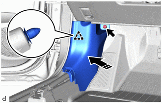
38.INSTALL COWL SIDE TRIM BOARD LH
|
|
Install in this Direction |
Engage the clip to install the cowl side trim board LH as shown in the illustration.
Install the clip.
62111C
39.INSTALL COWL SIDE TRIM BOARD RH
- HINT:
-
Use the same procedure as for the LH side.
67914B
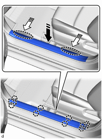
40.INSTALL FRONT DOOR SCUFF PLATE LH
|
|
Install in this Direction (1) |
|
|
Install in this Direction (2) |
Engage the guides and claws to install the front door scuff plate LH as shown in the illustration.
67913B
41.INSTALL FRONT DOOR SCUFF PLATE RH
- HINT:
-
Use the same procedure as for the LH side.
64997
42.INSTALL DECK FLOOR BOX LH
Install the deck floor box LH.
64995
43.INSTALL DECK FLOOR BOX RH
Install the deck floor box RH.
58410B
44.INSTALL DECK BOARD ASSEMBLY
Install the deck board assembly.
64330D
45.INSTALL PACKAGE TRAY TRIM PANEL ASSEMBLY (w/ Package Tray Trim)
Engage the hooks to install the package tray trim panel assembly.
46.INSTALL REAR SEAT ASSEMBLY
47.INSTALL FRONT SEAT ASSEMBLY LH
48.INSTALL FRONT SEAT ASSEMBLY RH
- HINT:
-
Use the same procedure as for the LH side.
55085
49.INSTALL NO. 2 HEATER TO REGISTER DUCT SUB-ASSEMBLY (for LHD)
55085
50.INSTALL NO. 2 HEATER TO REGISTER DUCT SUB-ASSEMBLY (for RHD)
55302C
51.INSTALL INSTRUMENT PANEL SUB-ASSEMBLY (for Integrated Type)
55302C
52.INSTALL INSTRUMENT PANEL SUB-ASSEMBLY (for Separate Type)