DTC C1640
Precautions: Precautions for Diagnosing Trouble · Precautions for RBS System · Precautions for Servicing RBS System · Precautions for Removing / Installing and Replacing RBS Control Module · Precautions for Control Systems · General safety (00)
DTC Detecting Condition and Trouble Area
| DTC detecting condition | Trouble area |
|---|---|
|
C1640: RBS Control Temporary Inhibition RBS control module detects this DTC if any one of the following conditions is met.
•Poor visibility of millimeter wave radar.
•High temperature in RBS control module. •Power supply for RBS control module is not between 10.0 and 15.5 V for 2 seconds continuously. •RBS control module received automatic brake temporary stop signal from ESP® control module. •RBS control module received invalid outside air temperature sensor signal from BCM. |
•Millimeter wave radar surface or millimeter wave radar cover
•RBS control module power supply / ground circuit •Charging system •Outside air temperature sensor •RBS control module |
Circuit Diagram
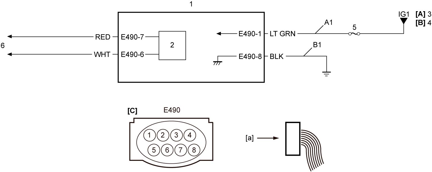
| [A]: | Ignition switch model | B1: | RBS control module ground circuit | 4. | IG1 relay |
| [B]: | Keyless push start model | 1. | RBS control module | 5. | “CRUISE” fuse |
| [C]: | RBS control module connector (View: [a]) | 2. | CAN driver | 6. | Each control module
•M16A model: CAN Communication System Circuit Diagram:M16A Model
•K14C model: CAN Communication System Circuit Diagram:K14C Model •D16AA model: CAN Communication System Circuit Diagram:D16AA Model |
| A1: | RBS control module power supply circuit | 3. | Ignition switch |
System Description
When RBS control module judges that the system impairs the original performance, RBS control module suspends frontal collision warning function, brake assist function, automatic brake function and adaptive cruise control, and outputs DTC C1640. However, when the cause of the suspension is eliminated, RBS control module turns off RBS indicator light, clears the DTC and resumes the system function automatically.
DTC Confirmation Procedure
1)Set ignition “ON”.
DTC Troubleshooting
NOTE:
•DTC C1640 can be detected as a current DTC but it is not stored as a history DTC.
•When any malfunction is detected on each parameter in the following table, “NG” indication is maintained. Therefore, after resuming the system to be normal, the factor of the malfunction can be checked in “Data List” of SUZUKI scan tool. The “NG” indication is maintained until the DTC is cleared.
•When any malfunction is detected on each parameter in the following table, “NG” indication is maintained. Therefore, after resuming the system to be normal, the factor of the malfunction can be checked in “Data List” of SUZUKI scan tool. The “NG” indication is maintained until the DTC is cleared.
1)Check each parameter in the table below using SUZUKI scan tool.
2)Diagnose the defective parameter according to diagnosis flow. If diagnosis flow does not correspond to the parameter, perform RBS System Check.
| Parameter | Value | Diagnosis flow |
|---|---|---|
| Radar Visibility | NG | [a] 
|
| RBS Control Module Temperature Condition | NG | [b]
|
| RBS Control Module Voltage Condition | NG | [c]
|
| ABS/ESP® Control Module Condition | NG | [d]
|
| Outside Air Temperature Condition | NG | [e]
|
Clearance of diagnostic information
1)Check that no DTC is indicated.
NOTE:
Perform troubleshooting for applicable DTC if any DTC is detected.
2)Clear DTC(s) using SUZUKI scan tool.
NOTE:
Perform “DTC clear” although DTC is not detected.
3)Select “Data List” mode and check that each of the following parameters is “OK”.
•Radar Visibility
•RBS Control Module Temperature Condition
•RBS Control Module Voltage Condition
•ABS/ESP® Control Module Condition
•Outside Air Temperature Condition
•RBS Control Module Temperature Condition
•RBS Control Module Voltage Condition
•ABS/ESP® Control Module Condition
•Outside Air Temperature Condition
4)Set ignition “OFF” and disconnect SUZUKI scan tool from DLC.
Diagnosis flow: [a]
NOTE:
•With the radiator grill installed, the millimeter wave radar cover cannot be removed. It is necessary to remove the radiator grill for visual inspection of the millimeter wave radar device (RBS control module).
•Even if millimeter wave radar surface is not soiled, RBS control module may detect poor visibility on millimeter wave radar and output DTC C1640 because diffused reflection is caused due to road conditions such as inside of tunnel, a road with concrete walls on both sides or weather conditions such as heavy rain or snow. If the vehicle is driven for about 2 minutes after the above conditions have improved, RBS control module clears the DTC and resumes the system function automatically.
•Even if millimeter wave radar surface is not soiled, RBS control module may detect poor visibility on millimeter wave radar and output DTC C1640 because diffused reflection is caused due to road conditions such as inside of tunnel, a road with concrete walls on both sides or weather conditions such as heavy rain or snow. If the vehicle is driven for about 2 minutes after the above conditions have improved, RBS control module clears the DTC and resumes the system function automatically.
| Step | Action | Yes | No |
|---|---|---|---|
| 1 |
DTC check
Is current DTC C1640 detected?
|
Go to Step 2.
|
Perform Clearance of diagnostic information and check that parameter “Radar Visibility” on SUZUKI scan tool is “OK”.
|
| 2 |
Visual inspection for soil on millimeter wave radar surface
1)Check millimeter wave radar cover and millimeter wave radar surface for soil or damage.
Is check result OK?
|
Perform Clearance of diagnostic information after switching ignition from “OFF” to “ON” and recheck DTC.
|
Clean or replace millimeter wave radar cover and/or millimeter wave radar device and perform Clearance of diagnostic informationafter switching ignition from “OFF” to “ON”, and then check that parameter “Radar Visibility” on SUZUKI scan tool is “OK”.
|
Diagnosis flow: [b]
| Step | Action | Yes | No |
|---|---|---|---|
| 1 |
DTC check
Is current DTC C1640 detected?
|
Go to Step 2.
|
Perform Clearance of diagnostic information and check that parameter “RBS Control Module Temperature Condition” on SUZUKI scan tool is “OK”.
|
| 2 |
DTC recheck
1)Set ignition “OFF” and leave the vehicle for a while avoiding direct sunshine.
2)Set ignition “ON”.
3)Recheck DTC.
Is current DTC C1640 detected?
|
Perform Clearance of diagnostic information and recheck DTC.
|
Perform Clearance of diagnostic information and check that parameter “RBS Control Module Temperature Condition” on SUZUKI scan tool is “OK”.
|
Diagnosis flow: [c]
| Step | Action | Yes | No |
|---|---|---|---|
| 1 |
DTC check
Is current DTC C1640 detected?
|
Go to Step 2.
|
Perform Clearance of diagnostic information and check that parameter “RBS Control Module Voltage Condition” on SUZUKI scan tool is “OK”.
|
| 2 |
Battery and charging system check
1)Check battery and charging system.
•Battery:
—M16A model:
—K14C model: —D16AA model:
•Charging system:
—M16A model:
—K14C model: —D16AA model: Is check result OK?
|
Go to Step 3.
|
Repair or replace defective part and perform Clearance of diagnostic information, and then recheck DTC.
|
| 3 |
RBS control module power supply circuit check
1)Check that ignition is “OFF”.
2)Disconnect “E490” connector.
3)Check for proper terminal connection to “E490” connector.
4)If connections are OK, set ignition “ON”.
5)Check that voltage between “A1” circuit and ground is battery voltage.
Is check result OK?
|
Go to Step 4.
|
Repair or replace defective wire harness and perform Clearance of diagnostic information, and then recheck DTC.
|
| 4 |
RBS control module ground circuit check
1)Set ignition “OFF”.
2)Check that resistance between “B1” circuit and ground is less than 1 Ω.
Is check result OK?
|
Perform Clearance of diagnostic information and recheck DTC.
|
Repair or replace defective wire harness and perform Clearance of diagnostic information, and then recheck DTC.
|
Diagnosis flow: [d]
| Step | Action | Yes | No |
|---|---|---|---|
| 1 |
DTC check
Is current DTC C1640 detected?
|
Go to Step 2.
|
Perform Clearance of diagnostic information and check that parameter “ABS/ESP® Control Module Condition” on SUZUKI scan tool is “OK”.
|
| 2 |
ESP® system check
1)Perform ESP® System Check.
Is check result OK?
|
Perform Clearance of diagnostic information and recheck DTC.
|
Repair defective part(s) of ESP® system and perform Clearance of diagnostic information, and then recheck DTC.
|
Diagnosis flow: [e]
| Step | Action | Yes | No |
|---|---|---|---|
| 1 |
DTC check
Is current DTC C1640 detected?
|
Go to Step 2.
|
Perform Clearance of diagnostic information and check that parameter “Outside Air Temperature Condition” on SUZUKI scan tool is “OK”.
|
| 2 |
DTC check
1)Check DTC in BCM.
Is there any DTC(s) detected?
|
Go to troubleshooting for applicable DTC and perform Clearance of diagnostic information, and then recheck DTC.
|
Go to Step 3.
|
| 3 |
Outside air temperature sensor check
1)Check outside air temperature sensor.
Is check result OK?
|
Perform Clearance of diagnostic information and recheck DTC.
|
Replace outside air temperature sensor and perform Clearance of diagnostic information, and then recheck DTC.
|