 |
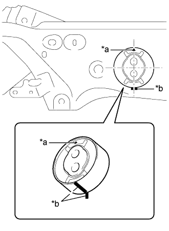
Put matchmarks on the rear suspension member and new rear No. 1 differential mount cushion.
| *a | Triangle Mark |
| *b | Matchmark |
- NOTICE:
- Install the rear No. 1 differential mount cushion with the triangle mark facing upward.
REAR SUSPENSION MEMBER > INSTALLATION |
| 1. INSTALL REAR NO. 1 DIFFERENTIAL MOUNT CUSHION |
|
Put matchmarks on the rear suspension member and new rear No. 1 differential mount cushion.
| *a | Triangle Mark |
| *b | Matchmark |
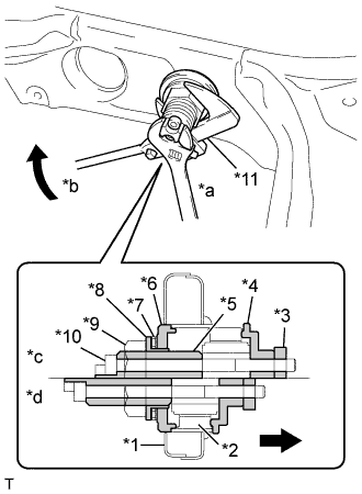 |
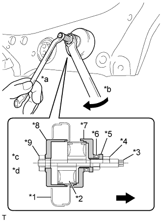
Using SST, install the rear No. 1 differential mount cushion.
| *1 | Rear Suspension Member |
| *2 | Rear No. 1 Differential Mount Cushion |
| *3 | SST(09571-01150) |
| *4 | SST(09571-01130) |
| *5 | SST(09571-01190) |
| *6 | SST(09571-01120) |
| *7 | SST(09571-01170) |
| *8 | SST(09571-01140) |
| *9 | SST(09571-01160) |
| *10 | SST(09571-01180) |
| *11 | SST(09922-10010) |
| *a | Hold |
| *b | Turn |
| *c | Start |
| *d | End |
 | Front side |
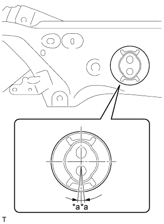 |
| *a | 3° |
| 2. INSTALL REAR NO. 2 DIFFERENTIAL MOUNT CUSHION |
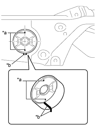 |
Put matchmarks on the rear suspension member and new rear No. 2 differential mount cushion.
| *a | Arrow |
| *b | Matchmark |
 |
Using SST, install the rear No. 2 differential mount cushion.
| *1 | Rear Suspension Member |
| *2 | Rear No. 2 Differential Mount Cushion |
| *3 | SST(09571-01090) |
| *4 | SST(09571-01070) |
| *5 | SST(09571-01050) |
| *6 | SST(09571-01080) |
| *7 | SST(09571-01040) |
| *8 | SST(09571-01030) |
| *9 | SST(09571-01060) |
| *a | Hold |
| *b | Turn |
| *c | Start |
| *d | End |
| Front side |
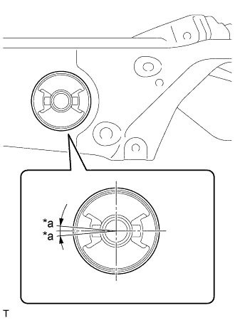 |
| *a | 5° |
| 3. TEMPORARILY INSTALL REAR UPPER CONTROL ARM ASSEMBLY LH |
Temporarily install the rear upper control arm assembly LH to the rear suspension member sub-assembly with the 2 bolts and 2 new nuts.
Temporarily install the rear upper control arm assembly LH to the axle carrier with the new bolt and a new nut.
| 4. TEMPORARILY INSTALL REAR UPPER CONTROL ARM ASSEMBLY RH |
| 5. INSTALL REAR SUSPENSION MEMBER SUB-ASSEMBLY |
Support the rear suspension member sub-assembly with an engine lifter using 4 attachments or equivalent tools.
Raise the rear suspension member sub-assembly until there is no clearance between the rear suspension member sub-assembly and the vehicle body.
While supporting the rear suspension member sub-assembly with a high transmission jack, using the 4 bolts B and 4 new bolts A, install the suspension member sub-assembly, front support rear LH, front support rear RH, rear support upper and rear support lower all together.
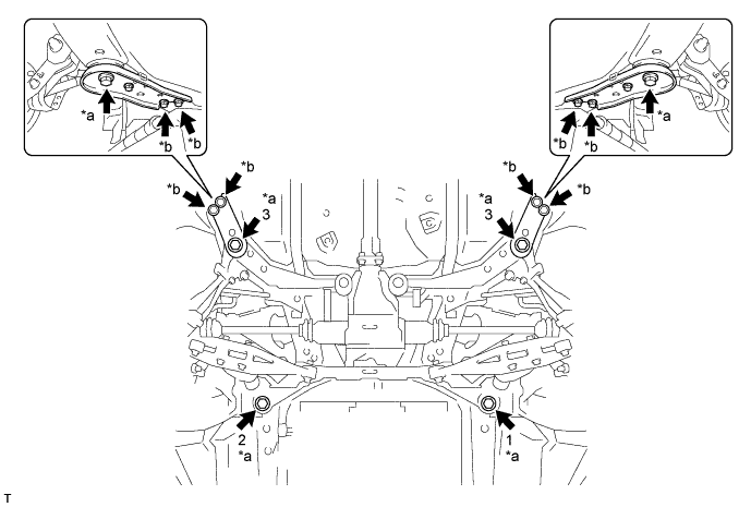
| *a | Bolt A (New bolt) | *b | Bolt B |
| 6. TEMPORARILY INSTALL TOE CONTROL LINK SUB-ASSEMBLY LH |
Install the toe control link sub-assembly LH and insert the toe adjust cam from the front of the vehicle. Then, install the No. 2 toe adjust plate and temporarily install a new nut.
| 7. TEMPORARILY INSTALL TOE CONTROL LINK SUB-ASSEMBLY RH |
| 8. TEMPORARILY INSTALL REAR NO. 2 SUSPENSION ARM ASSEMBLY LH |
Temporarily install the rear No. 2 suspension arm assembly LH to the rear suspension member with the bolt and a new nut.
| 9. TEMPORARILY INSTALL REAR NO. 2 SUSPENSION ARM ASSEMBLY RH |
| 10. TEMPORARILY INSTALL REAR SHOCK ABSORBER WITH COIL SPRING LH |
Temporarily install the rear shock absorber assembly to the rear No. 2 suspension arm with the bolt and a new nut.
| 11. TEMPORARILY INSTALL REAR SHOCK ABSORBER WITH COIL SPRING RH |
| 12. TEMPORARILY INSTALL REAR NO. 1 SUSPENSION ARM ASSEMBLY LH |
Temporarily install the rear No. 1 suspension arm assembly LH to the rear suspension member with the new bolt and new nut.
| 13. TEMPORARILY INSTALL REAR NO. 1 SUSPENSION ARM ASSEMBLY RH |
| 14. INSTALL REAR STABILIZER BAR |
| 15. TEMPORARILY TIGHTEN STABILIZER LINK SUB-ASSEMBLY (for LH Side) |
Temporarily install the rear stabilizer link sub-assembly to the rear No. 2 suspension arm assembly LH with the bolt and new nut.
| 16. TEMPORARILY TIGHTEN STABILIZER LINK SUB-ASSEMBLY (for RH Side) |
| 17. INSTALL PARKING BRAKE CABLE SUPPORT BRACKET (for LH Side) |
Install the parking brake cable support bracket with the bolt.
| 18. INSTALL PARKING BRAKE CABLE SUPPORT BRACKET (for RH Side) |
| 19. INSTALL NO. 2 FUEL TANK PROTECTOR (for Clamp Type) |
Install the No. 2 fuel tank protector with 2 new nuts and 2 clips.
| 20. INSTALL NO. 1 FUEL TANK PROTECTOR (for Clamp Type) |
Install the No. 1 fuel tank protector with 2 new nuts and 2 clips.
| 21. INSTALL NO. 3 FUEL TANK PROTECTOR (for Metal Type) |
Install the No. 3 fuel tank protector with a new nut and 2 clips.
| 22. INSTALL NO. 3 PARKING BRAKE CABLE ASSEMBLY |
Install the No. 3 parking brake cable assembly to the axle carrier with the clamp.
Install the No. 3 parking brake cable assembly to the rear suspension member lower stopper LH with the bolt.
| 23. INSTALL NO. 2 PARKING BRAKE CABLE ASSEMBLY |
| 24. INSTALL REAR AXLE CARRIER SUB-ASSEMBLY LH |
| 25. INSTALL REAR AXLE CARRIER SUB-ASSEMBLY RH |
| 26. INSTALL REAR DRIVE SHAFT ASSEMBLY LH |
| 27. INSTALL REAR DRIVE SHAFT ASSEMBLY RH |
| 28. INSTALL REAR DIFFERENTIAL CARRIER ASSEMBLY |
| 29. INSTALL PROPELLER WITH CENTER BEARING SHAFT ASSEMBLY |
| 30. INSTALL EXHAUST TAIL PIPE ASSEMBLY |
| 31. INSTALL REAR HEIGHT CONTROL SENSOR SUB-ASSEMBLY LH (w/ HID Headlight System) |
| 32. STABILIZE SUSPENSION |
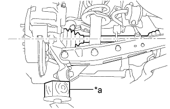 |
Jack up the axle carrier, with a wooden block placed between the jack and axle carrier, to apply load to the suspension so that the rear drive shaft assembly becomes level.
| *a | Wooden Block |
| 33. FULLY TIGHTEN REAR UPPER CONTROL ARM ASSEMBLY LH |
Fully tighten the nut on the axle carrier side of the upper control arm assembly LH.
Fully tighten the 2 nuts on the suspension member side of the upper control arm assembly LH.
| 34. FULLY TIGHTEN REAR UPPER CONTROL ARM ASSEMBLY RH |
| 35. FULLY TIGHTEN TOE CONTROL LINK SUB-ASSEMBLY LH |
Fully tighten the nut on the rear suspension member side.
| 36. FULLY TIGHTEN TOE CONTROL LINK SUB-ASSEMBLY RH |
| 37. TEMPORARILY INSTALL REAR NO. 2 SUSPENSION ARM ASSEMBLY LH |
Fully tighten the nut holding the rear shock absorber.
Fully tighten the nut on the rear suspension member sub-assembly side.
| 38. TEMPORARILY INSTALL REAR NO. 2 SUSPENSION ARM ASSEMBLY RH |
| 39. FULLY TIGHTEN STABILIZER LINK SUB-ASSEMBLY (for LH Side) |
Fully tighten the nut rear stabilizer link sub-assembly side.
| 40. FULLY TIGHTEN STABILIZER LINK SUB-ASSEMBLY (for RH Side) |
| 41. FULLY TIGHTEN REAR NO. 1 SUSPENSION ARM ASSEMBLY LH |
Fully tighten the bolt on the rear suspension member side of the rear No. 1 suspension arm assembly LH.
| 42. FULLY TIGHTEN REAR NO. 1 SUSPENSION ARM ASSEMBLY RH |
| 43. INSTALL REAR WHEELS |
| 44. INSPECT AND ADJUST REAR WHEEL ALIGNMENT |
| 45. VSC SENSOR NEUTRAL MEMORIZATION |
| 46. CHECK FOR SPEED SENSOR SIGNAL |
| 47. HEIGHT CONTROL SENSOR SIGNAL INITIALIZE (w/ HID Headlight System) |
| 48. ADJUST HEADLIGHT AIMING (w/ HID Headlight System) |