K114 MULTIDRIVE / CVT TRANSMISSION CONTROL CABLE INSTALLATION
PROCEDURE

 33820B
1.INSTALL TRANSMISSION CONTROL CABLE ASSEMBLY
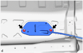
Pass the transmission control cable assembly into the vehicle and install the transmission control cable assembly to the vehicle body with the 2 nuts.
- Torque:
- 5.0 N*m (51 kgf*cm, 44 in.*lbf)
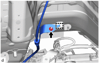
Engage the guide to connect the transmission control cable assembly to vehicle body.
Install the nut.
- Torque:
- 5.0 N*m (51 kgf*cm, 44 in.*lbf)
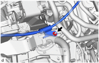
Install the transmission control cable assembly to the transmission control cable support with the nut.
- Torque:
- 5.0 N*m (51 kgf*cm, 44 in.*lbf)
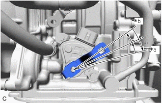
| *a | P Position |
| *b | N Position |
Turn the control shaft lever clockwise until it stops, then turn it counterclockwise 2 notches.
Install the transmission control cable assembly to the No. 1 transmission control cable bracket with a new clip.
Connect the transmission control cable assembly to the control shaft lever with the nut.
- Torque:
- 12 N*m (122 kgf*cm, 9 ft.*lbf)
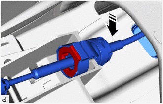

|
Install in this Direction |
Connect the transmission control cable assembly to the floor shift shift lever assembly.
- NOTICE:
-
Make sure that the transmission control cable assembly is securely locked.
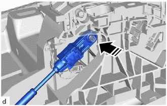
|
|
Install in this Direction |
Connect the end of the transmission control cable assembly to the floor shift shift lever assembly.
- NOTICE:
- ·
Before connecting the transmission control cable assembly, check that the park/neutral position switch and shift lever are in N.
·Install the end of the transmission control cable assembly so that the lock piece faces the driver side.
·Install the end of the transmission control cable assembly all the way to the base of the pin.
2.ADJUST SHIFT LEVER POSITION
58151
3.INSTALL FRONT NO. 1 FLOOR HEAT INSULATOR
Install the front No. 1 floor heat insulator to the vehicle body with the 3 nuts.
- Torque:
- 5.0 N*m (51 kgf*cm, 44 in.*lbf)
17410
4.INSTALL FRONT EXHAUST PIPE ASSEMBLY (TWC: Front and Rear Catalyst)
57533B
5.INSTALL FRONT FLOOR CENTER BRACE
74404A
6.INSTALL BATTERY CLAMP SUB-ASSEMBLY
89661
7.INSTALL ECM
17701
8.INSTALL AIR CLEANER CASE SUB-ASSEMBLY
17705
9.INSTALL AIR CLEANER CAP WITH AIR CLEANER HOSE
17751
10.INSTALL NO. 1 AIR CLEANER INLET
53141F
11.INSTALL RADIATOR COVER
12.INSTALL REAR CONSOLE BOX ASSEMBLY
33504F
13.INSTALL SHIFT LEVER KNOB SUB-ASSEMBLY
28800
14.INSTALL BATTERY
15.CONNECT CABLE TO NEGATIVE BATTERY TERMINAL
Click hereGeneral>MAINTENANCE>3ZR-FAE BATTERY>INSTALLATION
- NOTICE:
-
When disconnecting the cable, some systems need to be initialized after the cable is reconnected.
-
Click hereGeneral>INTRODUCTION>REPAIR INSTRUCTION>INITIALIZATION
16.INSPECT SHIFT LEVER POSITION
17.INSPECT FOR EXHAUST GAS LEAK
Click hereEngine / Hybrid System>3ZR-FAE (INTAKE / EXHAUST)>EXHAUST PIPE>INSTALLATION
- HINT:
-
Perform "Inspection After Repairs" after repairing or replacing the exhaust system.
-
Click hereEngine / Hybrid System>3ZR-FAE (ENGINE CONTROL)>SFI SYSTEM>INITIALIZATION
11212
18.INSTALL NO. 2 CYLINDER HEAD COVER
51444A
19.INSTALL REAR ENGINE UNDER COVER LH
51410
20.INSTALL NO. 1 ENGINE UNDER COVER