6AR-FSE LUBRICATION OIL PUMP REMOVAL
CAUTION / NOTICE / HINT
The necessary procedures (adjustment, calibration, initialization, or registration) that must be performed after parts are removed and installed, or replaced during timing chain cover sub-assembly removal/installation are shown below.
| Replaced Part or Performed Procedure | Necessary Procedure | Effect/Inoperative Function when Necessary Procedure not Performed | Link | |
|---|---|---|---|---|
|
*1: The vehicle height changes because of suspension or tire replacement. |
||||
| Battery terminal is disconnected/reconnected | Perform steering sensor zero point calibration | Lane departure alert system (w/ Steering Control) | ( ) |
|
| Pre-collision system | ||||
| Memorize steering angle neutral point | Parking assist monitor system | ()
|
||
| Panoramic view monitor system | ()
|
|||
| Replacement of ECM | Perform Vehicle Identification Number (VIN) or frame number registration | MIL comes on | ()
|
|
| Perform code registration (Immobiliser system) | Engine start function | See Service Bulletin for the registration method. | ||
·
Replacement of engine assembly ·
Gas leak from exhaust system is repaired |
Inspection after repair | ·
Poor idle, etc. ·
Engine start function, etc. |
()
|
|
| Replacement of automatic transaxle assembly | Perform the following procedures in the order shown:
1.
Reset Memory 2.
Input transaxle compensation code into ECM 3.
Perform road test to allow ECM to learn |
·
Large shift shock ·
Deterioration of fuel efficiency |
()for U761E Initialization
( )for U761E Registration
|
|
| Replacement of ECM
(If possible, read the transaxle compensation code from the previous ECM) |
Possible | Perform the following procedures in the order shown:
1.
Reset Memory 2.
Transfer transaxle compensation code 3.
Perform road test to allow ECM to learn |
||
| Impossible | Perform the following procedures in the order shown:
1.
Reset Memory 2.
Reset transaxle compensation code 3.
Perform road test to allow ECM to learn |
|||
| Replacement of ECM | Perform code registration (Immobiliser function) | ·
Wireless door lock control system ·
Smart Entry and Start System (for Entry Function) ·
Smart Entry and Start System (for Start Function) ·
Steering lock function |
See Service Bulletin for the registration method. | |
| Suspension, tires, etc.*1 | Rear television camera assembly optical axis (Back camera position setting) | Parking assist monitor system | ()for Initialization
( )for Calibration
|
|
·
Television camera controller initialization ·
Adjust steering angle ·
Rear television camera assembly optical axis (Back camera position setting) |
Panoramic view monitor system | ()for Initialization
( )for Calibration
|
||
| Replacement of front bumper assembly | Front television camera view adjustment | |||
| Front wheel alignment adjustment | Perform system variant learning and acceleration sensor zero point calibration. | ·
VSC disabled or malfunctioning ·
DTCs are output ·
Slip indicator light illuminated ·
ABS warning light illuminated |
()
|
|
PROCEDURE

 1.INSTALL ENGINE ASSEMBLY TO ENGINE STAND
19500
2.REMOVE IGNITION COIL ASSEMBLY
12262
3.DISCONNECT NO. 2 VENTILATION HOSE
4.REMOVE FUEL PUMP PROTECTOR
5.DISCONNECT NO. 2 FUEL TUBE SUB-ASSEMBLY
23811B
6.REMOVE NO. 1 FUEL PIPE
23801P
7.REMOVE NO. 1 FUEL PIPE SUB-ASSEMBLY
23021
8.REMOVE FUEL PUMP WITH SEAL SUB-ASSEMBLY
25625
9.REMOVE EGR VALVE BRACKET
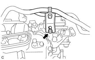
Remove the engine cover joint and separate the fuel hose bracket from the EGR valve bracket.
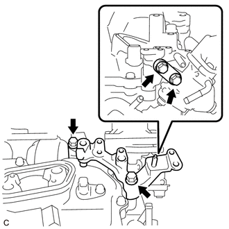
Remove the 4 bolts and 2 EGR valve brackets.
11201
10.REMOVE CYLINDER HEAD COVER SUB-ASSEMBLY
11301K
11.REMOVE CRANKSHAFT POSITION SENSOR
13471
12.REMOVE CRANKSHAFT PULLEY
15370
13.REMOVE CAMSHAFT TIMING OIL CONTROL SOLENOID ASSEMBLY
16620
14.REMOVE V-RIBBED BELT TENSIONER ASSEMBLY
12315A
15.REMOVE ENGINE MOUNTING BRACKET RH
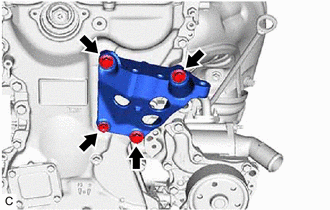
Remove the 4 bolts and engine mounting bracket RH.
11302
16.REMOVE TIMING CHAIN COVER SUB-ASSEMBLY
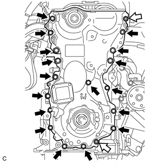

|
Bolt |

|
Nut |
Remove the 17 bolts and 2 nuts.
Remove the timing chain cover sub-assembly by prying between the timing chain cover sub-assembly and cylinder head sub-assembly, camshaft housing sub-assembly, cylinder block and stiffening crankcase assembly with a screwdriver as shown in the illustration.
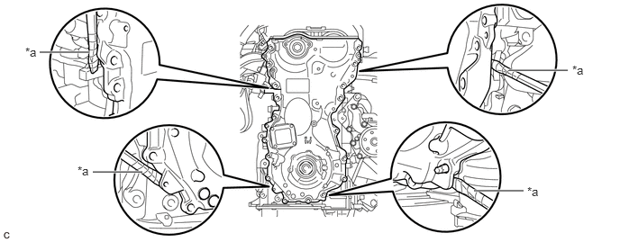
| *a | Protective Tape | - | - |
- NOTICE:
-
Be careful not to damage the contact surfaces of the cylinder head sub-assembly, camshaft housing sub-assembly, cylinder block, stiffening crankcase assembly or timing chain cover sub-assembly.
- HINT:
-
Tape the screwdriver tip before use.
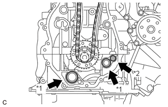
| *1 | Oil Pump Gasket |
| *2 | Oil Hole Cover Gasket |
Remove the 2 oil pump gaskets and oil hole cover gasket from the stiffening crankcase assembly.
11301C
17.REMOVE TIMING CHAIN COVER OIL SEAL
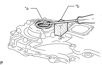
| *a | Protective Tape |
| *b | Wooden Block |
Using a screwdriver and wooden block, pry out the timing chain cover oil seal.
- NOTICE:
-
Do not damage the surface of the timing chain cover oil seal press fit hole.
- HINT:
-
Tape the screwdriver tip before use.