1BZ-FPE ENGINE MECHANICAL CYLINDER BLOCK REASSEMBLY
PROCEDURE

 13201
1.ASSEMBLE PISTON AND CONNECTING ROD
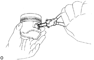
Install a new snap ring on one side of the piston pin hole.
Gradually heat the piston to 60 °C (140 °F).
Coat the piston pin with engine oil.
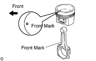
Align the front marks of the piston and connecting rod, and push in the piston pin with your thumb.
Install a new snap ring on the other side of the piston pin hole.
13011
2.INSTALL PISTON RINGS
Install the coil by hand.
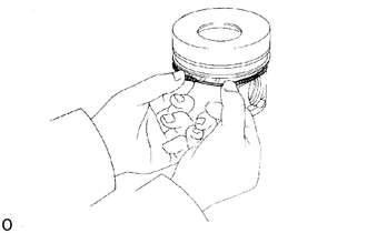
Install a piston ring expander, install the oil ring.
- HINT:
-
-
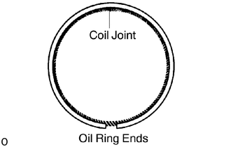
Face the end gap of the oil ring in the opposite direction of coil joint.
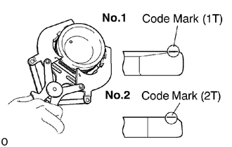
Using a piston ring expander, install the No.1 and No.2 piston rings with the code mark facing upward.
Code mark:
No.1: 1T
No.2: 2T
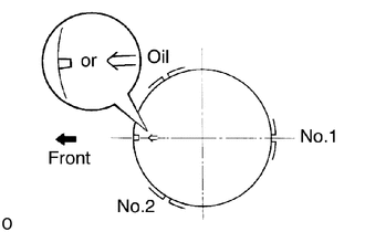
Position the piston rings so that the ring ends are as shown.
- NOTICE:
-
Do not align the ring ends.
13041
3.INSTALL CONNECTING ROD BEARING
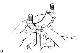
Align the bearing claw with the groove of the connecting rod or connecting rod cap.
Install the bearing in the connecting rod and connecting rod cap.
- HINT:
- ·
Thoroughly clean all parts to be assembled.
·Before installing the parts, apply fresh engine oil to all sliding and rotating surfaces.
·Replace all gaskets and oil seals with new ones.
13751
4.INSTALL VALVE LIFTERS
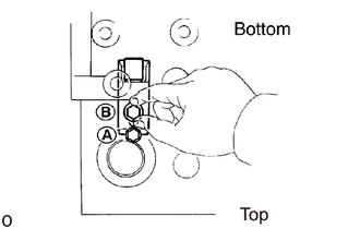
Install bolt (A) to the cylinder block with a new gasket.
- Torque:
7.5 N*m (76 kgf*cm, 66 in.*lbf)
Install the valve lifter so that the tip of bolt (A) fits in the groove.
Install bolt (B) with a new gasket by hand, check that its tip is inside the long hole.
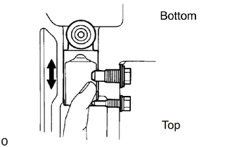
Torque bolt (B).
- Torque:
37 N*m (375 kgf*cm, 28 ft*lbf)
- HINT:
-
Check that the valve lifter moves smoothly up and down.
13613C
5.INSTALL OIL NOZZLES AND CHECK VALVES
6.INSTALL MAIN BEARINGS
- HINT:
-
Upper bearings have an oil groove and oil hole, lower bearings do not.
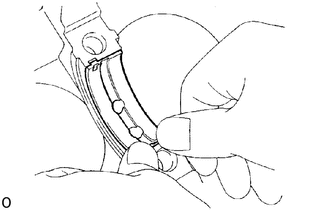
Align the bearing claw with the claw groove of the cylinder block, and push in the 5 upper bearings.
Align the bearing claw with the claw groove of the main bearing cap, and push in the 5 lower bearings.
7.INSTALL UPPER THRUST WASHERS
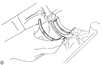
Install the 2 thrust washers under the No.3 journal position of the cylinder block with the oil grooves facing outward.
13411
8.PLACE CRANKSHAFT ON CYLINDER BLOCK
9.INSTALL MAIN BEARING CAPS AND LOWER THRUST WASHERS
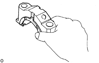
Install the 2 lower thrust washers on the No.3 main bearing cap with the grooves facing outward.
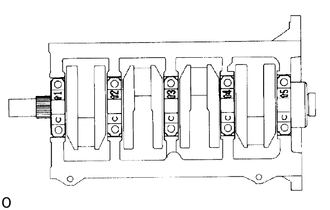
Install the 5 main bearing caps in their proper locations.
Apply a light coat of the engine oil on the threads and under the bolt heads of the main bearing caps.
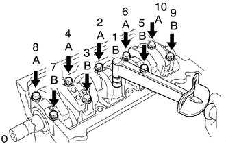
Install and uniformly tighten the 10 bolts of the main bearing caps, in several passes, in the sequence shown.
- Torque:
200 N*m (2,039 kgf*cm, 148 ft*lbf)
- HINT:
-
Each bolt length is indication in the illustration.
Bolt length:
A: 129.5 mm (5.098 in.)
B: 93.5 mm (3.681 in.)
Check that the crankshaft turns smoothly.
10.CHECK CRANKSHAFT THRUST CLEARANCE
13101
11.INSTALLATION PISTON AND CONNECTING ROD ASSEMBLIES
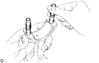
Cover the connecting rod bolts with a short piece of hose to protect the crankshaft and cylinder bore form damage.
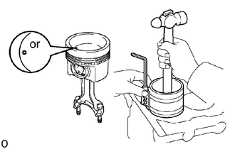
Using a piston ring compressor, push the correctly numbered piston and connecting rod assembly into the cylinder with the front mark of the piston facing forward.
13201
12.INSTALL CONNECTING ROD CAPS
Place connecting rod cap on connecting rod
Match the numbered connecting rod cap with the connecting rod.
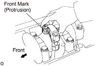
Install the connecting rod cap with the front mark facing forward.
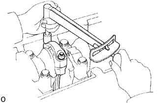
Install connecting rod cap nuts
- HINT:
- ·
The connecting rod cap nuts are tightened in 2 progressive steps (steps (b) and (d)).
·If any connecting rod bolt is broken or deformed, replace it.
Apply a light of engine oil on the threads and under the heads of the connecting rod cap bolts and nuts.
Install and alternately tighten the nuts of the connecting rod cap in several passes.
- Torque:
68.6 N*m (700 kgf*cm, 51 ft*lbf)
If any one of the connecting rod cap nuts does not meet the torque specification, replace the cap nuts.
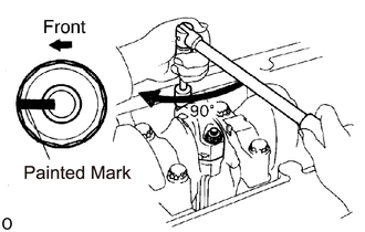
Mark the front of the connecting rod cap nuts with paint.
Retighten the connecting rod cap nut s 90 ° as shown.
Check that the painted mark is now at a 90 ° angle to the front.
Check that the crankshaft turns smoothly.
13201
13.CHECK CONNECTING ROD THRUST CLEARANCE
11381
14.INSTALL REAR OIL SEAL RETAINER
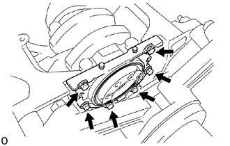
Install a new gasket and the retainer with the 6 bolts.
- Torque:
18.5 N*m (189 kgf*cm, 14 ft*lbf)
12311
15.INSTALL ENGINE MOUNTING BRACKETS
- Torque:
44 N*m (449 kgf*cm, 32 ft*lbf)
13613C
16.INSTALL OIL NOZZLE FOR TIMING GEARS
Click hereEngine / Hybrid System>1BZ-FPE (ENGINE MECHANICAL)>TIMING GEAR>INSTALLATION
- Torque:
13 N*m (133 kgf*cm, 10 ft*lbf)
83530
17.INSTALL OIL PRESSURE SWITCH
15710
18.INSTALL OIL COOLER AND OIL FILTER ASSEMBLIES
12101
19.INSTALL TIMING GEAR CASE (OIL PUMP), OIL STRAINER AND OIL PAN
13523
20.INSTALL TIMING GEARS AND CAMSHAFT
11101
21.INSTALL CYLINDER HEAD
11452
22.INSTALL OIL DIPSTICK GUIDE AND OIL DIPSTICK
23.INSTALL WATER DRAIN UNION
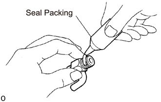
Apply seal packing to 2 or 3 threads.
- Seal packing:
Part No. 08826-00100 or equivalent
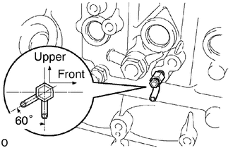
Install the drain union.
- Torque:
70 N*m (714 kgf*cm, 52 ft*lbf)
- HINT:
-
After applying the specified torque, rotate the drain union clockwise until its drain hole is facing downward.
16100
24.INSTALL WATER PUMP
27020
25.INSTALL ALTERNATOR BRACKET AND ALTERNATOR
Apply a light of engine oil on the threads and under the heads of the alternator bracket bolts and pivot bolt.
Install the alternator bracket with the 3 bolts.
- Torque:
98 N*m (1,000 kgf*cm, 72 ft*lbf)
Install the alternator with the pivot bolt.
26.DISCONNECT ENGINE FROM ENGINE STAND
11355
27.INSTALL REAR END PLATE
Install the rear end plate with the bolt.
- Torque:
18.5 N*m (189 kgf*cm, 14 ft*lbf)
28.INSTALL FLYWHEEL HOUSING
13405
29.INSTALL FLYWHEEL
Install the flywheel on the crankshaft.
Apply a light of engine oil on the threads and under the heads of the flywheel bolts.
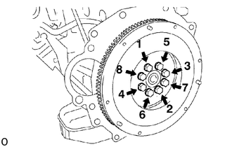
Install and uniformly tighten the bolts, in several passes, in the sequence shown.
- Torque:
160 N*m (1,630 kgf*cm, 118 ft*lbf)