METER / GAUGE / DISPLAY METER / GAUGE SYSTEM AdBlue Gauge Malfunction
DESCRIPTION
The combination meter assembly receives remaining urea level signals from the ECM via CAN communication. The combination meter assembly operates the remaining AdBlue gauge based on the received remaining urea level signals.
WIRING DIAGRAM
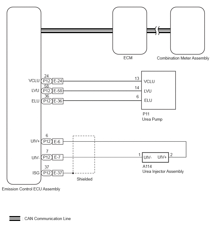
CAUTION / NOTICE / HINT
- NOTICE:
- ·
Since CAN communication is used, first perform the communication function check in "How to Proceed with Troubleshooting" to confirm that there are no communication malfunctions before proceeding with troubleshooting.
·When replacing the combination meter assembly, be sure to replace it with a new one. If a combination meter assembly that was installed in another vehicle is used, the information stored in the combination meter assembly will not match the information from the vehicle, and may cause a DTC to be output.
·When checking the remaining amount of urea solution, be sure to stop the vehicle on a level surface.
·When refilling urea solution, turn the ignition switch off and add 5 liters (5.3 US qts, 4.4 Imp. qts) or more.
- HINT:
-
If too little is added, it may not be reflected on the remaining AdBlue gauge.
PROCEDURE
Turn the ignition switch to ON.
Using the GTS, enter the following menus: Health Check
Check for DTCs.
- Result:
Result Proceed to No DTC is output A DTC is output B
A
B
Using the GTS, perform the Active Test according to the display on the tester. (Click hereVehicle Interior>METER / GAUGE / DISPLAY>METER / GAUGE SYSTEM>DATA LIST / ACTIVE TEST)
| Tester Display | Measurement Item | Control Range |
|---|---|---|
| Fuel Meter Operation (Reductant) | AdBlue gauge | OFF, Sender E, Empty, 1/4, 1/2, 3/4, Full or Sender F |
- OK:
The Active Test is performed normally
- Result:
Proceed to OK NG
OK
NG
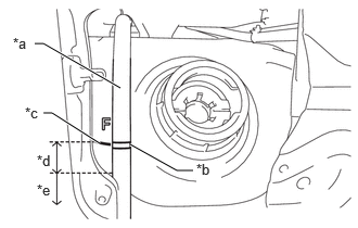
| *a | Refill Check Tube |
| *b | F Line (Refill Check Tube Side) |
| *c | F Line (Urea Tank Sub-assembly Side) |
| *d | Within 20 mm (0.787 in.) |
| *e | 21 mm (0.827 in.) or Less |
Check the urea tank sub-assembly level from the refill check tube.
- Result:
Urea Tank Level Proceed to Level is within 20 mm (0.787 in.) from bottom of "F" line A Level is 21 mm (0.827 in.) or less from bottom of "F" line B
A
B
Turn the ignition switch off and wait for 1 minute or more.
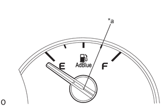
| *a | Remaining AdBlue Gauge "3/4" |
Turn the ignition switch to ON and check the position indicated in the remaining AdBlue gauge.
- Result:
Remaining AdBlue Gauge Position Proceed to 3/4 or more A Less than 3/4 B
A
B
Turn the ignition switch off, wait 1 minute, and then drain 8.5 liters (9.0 US qts, 7.5 Imp. qts) or more of urea solution (AdBlue).
Click hereEngine / Hybrid System>N04C-WA (EMISSION CONTROL)>UREA TANK>REMOVAL
Turn the ignition switch to ON and check the position indicated in the remaining AdBlue gauge.
- Result:
Result Proceed to Remaining AdBlue gauge changes A Remaining AdBlue gauge does not change B
A
B
Turn the ignition switch to ON.
Using the GTS, enter the following menus: Health Check
Check for DTCs.
- Result:
Result Proceed to No DTC is output A DTC is output B
A
B
- HINT:
-
Check the condition inside the urea tank sub-assembly on the assumption that the urea pump level sensor (float) did not operate due to a temporary factor.
Check if there is anything abnormal with the external appearance of the urea tank sub-assembly.
Check the installation condition of the urea tank sub-assembly and urea pump.
Check if there is entry of much dirt or other foreign matter inside the urea tank sub-assembly.
Check that there is no foreign matter adhering to the urea pump level sensor (float).
Visually check that the refill check tube is not clogged or blocked.
Shake the refill check tube and check for changes in the liquid surface caused by vibration, to check for any clogging or blockage.
- Result:
Result Proceed to Normal A There is something abnormal with the external appearance of the urea tank sub-assembly B There is something abnormal with the installation of the urea tank sub-assembly or urea pump C There is entry of much dirt or other foreign matter inside the urea tank sub-assembly D There is foreign matter adhering to the urea pump level sensor (float) E There is an abnormality in the refill check tube F
A
B
C
D
E
F
- HINT:
-
Clean the refill check tube with water or replace it.
- NOTICE:
-
Be careful when cleaning, as water entering the urea tank sub-assembly during cleaning could thin the urea solution (AdBlue) and cause a DTC to be output.
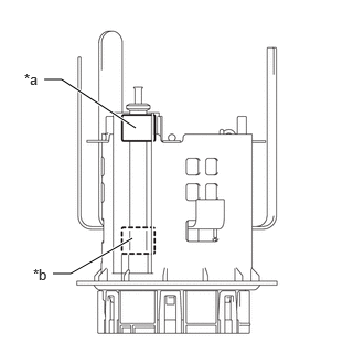
| *a | Float Position (Upper End) |
| *b | Float Position (Lower End) |
Check that the level sensor (float) moves smoothly between the upper end and lower end.
- Result:
Result Proceed to Float moves smoothly A Float does not move smoothly B
A
B
Remove the urea pump. (Click hereEngine / Hybrid System>N04C-WA (EMISSION CONTROL)>UREA PUMP>REMOVAL)
Inspect the urea pump. (Click hereEngine / Hybrid System>N04C-WA (EMISSION CONTROL)>UREA PUMP>INSPECTION)
- Result:
Proceed to OK NG
OK
NG
Turn the ignition switch to ON and check the position indicated in the remaining AdBlue gauge.
- NOTICE:
-
If the remaining AdBlue gauge does not indicate a level near the "E" line, perform step 12 (Check Harness and Connector (Urea Injector Assembly Circuit)).
Turn the ignition switch off, wait 1 minute or more, and then add 10 liters (10.6 US qts, 8.8 Imp. qts) or more of urea solution (AdBlue).
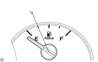
| *a | Remaining AdBlue Gauge "1/4" |
Turn the ignition switch to ON and check the position indicated in the remaining AdBlue gauge.
- Result:
Remaining AdBlue Gauge Position Proceed to 1/4 or more A Less than 1/4 B
A
B
While checking the refill check tube, add urea solution until the tank level is half full or more.
Remove the urea injector assembly from the front exhaust pipe assembly.
- HINT:
- ·
Do not remove the urea injector assembly from the urea tube with heater assembly.
·Use a cover, etc., to prevent foreign matter from entering the exhaust pipe.
Prepare a bucket or other receptacle for collecting urea solution from the urea injector assembly.
Connect the GTS to the DLC3.
Turn the ignition switch to ON.
Turn the GTS on.
Enter the following menus: Powertrain / Urea Selective Catalytic Reduction / Utility / Reductant Injection / Pattern 3 to 1
Perform "Pattern 3" to "Pattern 1" and check the urea solution injection volume.
- Standard Value:
Reductant Injection Urea Solution Injection Volume Pattern 3 45 to 55 cc (2.7 to 3.4 cu.in.) Pattern 2 16 to 24 cc (1.0 to 1.5 cu.in.) Pattern 1 7 to 13 cc (0.4 to 0.8 cu.in.)
- NOTICE:
-
Repeat 3 times. Must be within standard value once.
- HINT:
-
Crystallized urea solution dissolves in urea solution, so blockages can be cleared by repeatedly supplying and injecting urea solution.
-
Therefore, even if crystals accumulate on the tip of the injector, the above injection is possible and it is not a malfunction.
- Result:
Proceed to OK NG
OK
NG
- SST
- 09843-E7020
Disconnect the P12 connector of the emission control ECU assembly.
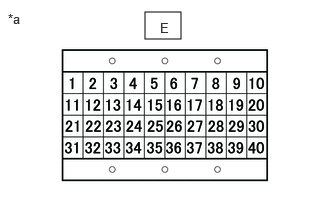
| *a | No. 2 Signal Check Wiring Harness Probe Connector |
Connect SST (No. 2 signal check wiring harness) to the emission control ECU assembly connector on the vehicle side (do not connect it to the emission control ECU assembly).
Measure the resistance according to the value(s) in the table below.
- Standard Resistance:
Tester Connection Switch Condition Specified Condition E-6 (UIV+) - E-7 (UIV-) Ignition switch off 17 Ω or less
- Result:
Proceed to OK NG
OK
NG
Remove the urea injector assembly from the front exhaust pipe assembly.
- HINT:
- ·
Do not remove the urea injector assembly from the urea tube with heater assembly.
·Use a cover, etc., to prevent foreign matter from entering the exhaust pipe.
Connect the GTS to the DLC3.
Turn the ignition switch to ON.
Turn the GTS on.
Enter the following menus: Powertrain / Urea Selective Catalytic Reduction / Utility / Pressure Rising Diagnosis (Leak Test).
Perform the Utility. Check for urea solution leaks in the urea injector assembly and between the urea injector assembly and urea pump.
- OK:
No urea solution leaks in the urea injector assembly and between the urea injector assembly and urea pump
- Result:
Proceed to OK NG
- HINT:
-
If the Utility fails, troubleshoot the error message and perform the Utility again.
OK
NG
Remove the urea injector assembly.
Click hereEngine / Hybrid System>N04C-WA (EMISSION CONTROL)>UREA INJECTOR>REMOVAL
Inspect the urea injector assembly.
Click hereEngine / Hybrid System>N04C-WA (EMISSION CONTROL)>UREA INJECTOR>INSPECTION
- Result:
Proceed to OK NG
OK
NG
Turn the ignition switch off, wait 1 minute, and then drain 5 liters (5.3 US qts, 4.4 Imp. qts) or more of urea solution (AdBlue).
Click hereEngine / Hybrid System>N04C-WA (EMISSION CONTROL)>UREA TANK>REMOVAL
Turn the ignition switch to ON and check the position indicated in the remaining AdBlue gauge.
- Result:
Result Proceed to Remaining AdBlue gauge changes A Remaining AdBlue gauge does not change B
A
B
- HINT:
-
Check the condition inside the urea tank sub-assembly on the assumption that the urea pump level sensor (float) did not operate due to a temporary factor.
Check if there is anything abnormal with the external appearance of the urea tank sub-assembly.
Check the installation condition of the urea tank sub-assembly and urea pump.
Check if there is entry of much dirt or other foreign matter inside the urea tank sub-assembly.
Check that there is no foreign matter adhering to the urea pump level sensor (float).
Visually check that the refill check tube is not clogged or blocked.
Shake the refill check tube and check for changes in the liquid surface caused by vibration, to check for any clogging or blockage.
- Result:
Result Proceed to Normal A There is something abnormal with the external appearance of the urea tank sub-assembly B There is something abnormal with the installation of the urea tank sub-assembly or urea pump C There is entry of much dirt or other foreign matter inside the urea tank sub-assembly D There is foreign matter adhering to the urea pump level sensor (float) E There is an abnormality in the refill check tube F
A
B
C
D
E
F
- HINT:
-
Clean the refill check tube with water or replace it.
- NOTICE:
-
Be careful when cleaning, as water entering the urea tank sub-assembly during cleaning could thin the urea solution (AdBlue) and cause a DTC to be output.
| *a | Float Position (Upper End) |
| *b | Float Position (Lower End) |
Check that the level sensor (float) moves smoothly between the upper end and lower end.
- Result:
Result Proceed to Float moves smoothly A Float does not move smoothly B
A
B
Remove the urea pump. (Click hereEngine / Hybrid System>N04C-WA (EMISSION CONTROL)>UREA PUMP>REMOVAL)
Inspect the urea pump. (Click hereEngine / Hybrid System>N04C-WA (EMISSION CONTROL)>UREA PUMP>INSPECTION)
- Result:
Proceed to OK NG
OK
NG
Turn the ignition switch to ON and check the position indicated in the remaining AdBlue gauge.
- NOTICE:
-
If the remaining AdBlue gauge does not indicate a level near the "E" line, perform step 20 (Check Harness and Connector (Urea Injector Assembly Circuit)).
Turn the ignition switch off, wait 1 minute or more, and then add 10 liters (10.6 US qts, 8.8 Imp. qts) or more of urea solution (AdBlue).
| *a | Remaining AdBlue Gauge "1/4" |
Turn the ignition switch to ON and check the position indicated in the remaining AdBlue gauge.
- Result:
Remaining AdBlue Gauge Position Proceed to 1/4 or more A Less than 1/4 B
A
B
- SST
- 09843-E7020
Disconnect the P12 connector of the emission control ECU assembly.
| *a | No. 2 Signal Check Wiring Harness Probe Connector |
Connect SST (No. 2 signal check wiring harness) to the emission control ECU assembly connector on the vehicle side (do not connect it to the emission control ECU assembly).
Measure the resistance according to the value(s) in the table below.
- Standard Resistance:
Tester Connection Switch Condition Specified Condition E-6 (UIV+) - E-7 (UIV-) Ignition switch off 17 Ω or less
- Result:
Proceed to OK NG
OK
NG
Turn the ignition switch off and wait for 1 minute or more.
| *a | Remaining AdBlue Gauge "3/4" |
Turn the ignition switch to ON and check the position indicated in the remaining AdBlue gauge.
- Result:
Remaining AdBlue Gauge Position Proceed to 3/4 or more A Less than 3/4 B
A
B
Turn the ignition switch off, wait 1 minute, and then add 5 liters (5.3 US qts, 4.4 Imp. qts) or more of urea solution (AdBlue).
Click hereEngine / Hybrid System>N04C-WA (EMISSION CONTROL)>UREA TANK>REFILL
Turn the ignition switch to ON and check the position indicated in the remaining AdBlue gauge.
- Result:
Result Proceed to Remaining AdBlue gauge changes A Remaining AdBlue gauge does not change B
A
B