N04C-UH FUEL FUEL SUPPLY PUMP INSTALLATION
PROCEDURE

 13613
1.INSTALL INJECTION PUMP DRIVE GEAR
Install a new O-ring onto the timer cover.
Install the timer cover onto the injection or supply pump with the 2 bolts.
- Torque:
29 N*m (291 kgf*cm, 21 ft.*lbf)
Install the crankshaft angle sensor plate and the drive gear with the nut.
- Torque:
64 N*m (650 kgf*cm, 47 ft.*lbf)
22100
2.INSTALL INJECTION OR SUPPLY PUMP ASSEMBLY
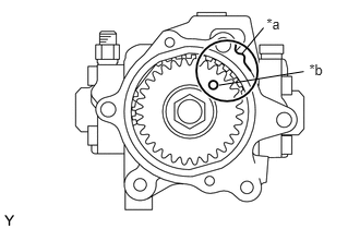
Install a new O-ring onto the timer cover.
| *a | Matchmark |
| *b | Hole |
Turn the drive gear and align the hole with the matchmark as shown in the illustration.
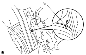
Check that the No. 1 cylinder is at TDC/ compression.
| *a | Timing Mark |
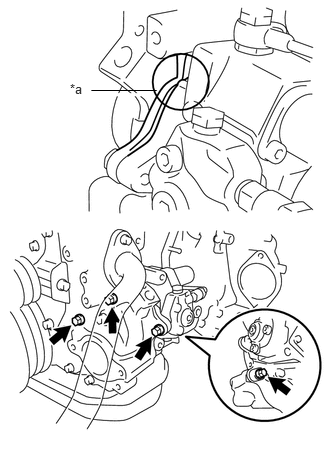
Align the matchmarks of the timer cover and the front end plate, and then install the supply pump assembly with the 4 bolts.
| *a | Matchmark |
- Torque:
29 N*m (291 kgf*cm, 21 ft.*lbf)
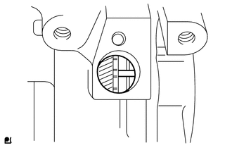
When the crankshaft position sensor's installation hole can be accessed directly:
Check that the knock pin of the injection pump drive gear is at the center of the hole. Then, proceed to step (g).
If not, perform steps (b), (c), and (d) again.
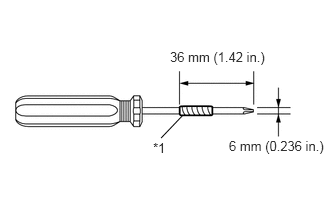
When the crankshaft position sensor installation hole cannot be accessed directly:
| *1 | Vinyl Tape |
Tape the screwdriver as shown in the illustration.
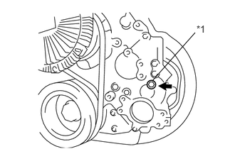
Remove the service plug and gasket from the timing chain or belt cover sub-assembly.
| *1 | Service Plug |
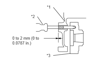
Insert the screwdriver into the service plug hole.
| *1 | Timing Chain Cover |
| *2 | Screwdriver |
| *3 | Drive Gear |
Check that the tape end and timing chain or belt cover sub-assembly are aligned as shown in the illustration.
If not, perform steps (b) and (c) again.
Install the service plug and a new gasket to the timing chain cover sub-assembly.
- Torque:
13 N*m (133 kgf*cm, 10 ft.*lbf)
Install the holder clip with the bolt.
- Torque:
29 N*m (291 kgf*cm, 21 ft.*lbf)
Connect the 2 connectors.
11301K
3.INSTALL CRANKSHAFT POSITION SENSOR
23803H
4.INSTALL FUEL RETURN PIPE SUB-ASSEMBLY
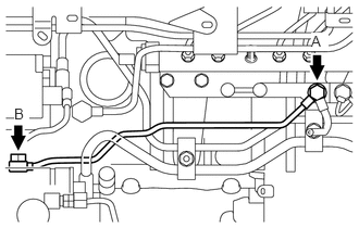
Temporarily install the fuel return pipe sub-assembly and 3 new gaskets with the 2 union bolts.
Tighten the 2 union bolts.
- Torque:
- Bolt A:
20 N*m (204 kgf*cm, 15 ft.*lbf)
- Bolt B:
10 N*m (102 kgf*cm, 7 ft.*lbf)
23801L
5.INSTALL FUEL FILTER TO INJECTION PUMP FUEL PIPE SUB-ASSEMBLY
Temporarily install the fuel filter to injection pump fuel pipe with the union nuts.
Using a union nut wrench (17 mm), tighten the fuel filter to injection pump fuel pipe with the 2 union nuts.
- Torque:
35 N*m (357 kgf*cm, 26 ft.*lbf)
- NOTICE:
- ·
If the supply pump assembly has been replaced, the fuel filter to injection pump fuel pipe must also be replaced.
·Refer to the torque above when not using the union nut wrench. When using the union nut wrench, calculate the torque in accordance with the lengths of the union nut wrench and torque wrench.
Click hereGeneral>INTRODUCTION>REPAIR INSTRUCTION>PRECAUTION
Install the pipe clamp with the nut. Tighten the nut until the clamp's edges make contact with the engine side clamp's edges.
6.INSTALL NO. 1 HARNESS BRACKET
Install the No. 1 wire harness bracket with the 2 bolts.
- Torque:
29 N*m (291 kgf*cm, 21 ft.*lbf)
7.INSTALL NO. 2 HARNESS BRACKET
23807
8.INSTALL FUEL DELIVERY PIPE SUB-ASSEMBLY
Install 2 new gaskets and the fuel delivery pipe with the union bolt.
- Torque:
25 N*m (255 kgf*cm, 18 ft.*lbf)
23271H
9.CONNECT NO. 1 FUEL HOSE RETURN TUBE
Connect the fuel hose.
22100A
10.CONNECT INJECTION PUMP TO FUEL FILTER FUEL HOSE OR PIPE
Connect the fuel hose.
11.INSTALL NO. 2 INTAKE PIPE WITH EGR VALVE
16206
12.INSTALL WATER BY-PASS PIPE SUB-ASSEMBLY
17113
13.INSTALL INTAKE PIPE WITH VENTURI ASSEMBLY
15301
14.INSTALL OIL DIPSTICK GUIDE
17342P
15.INSTALL NO. 2 AIR HOSE
44360
16.INSTALL VANE PUMP OIL RESERVOIR ASSEMBLY
25625B
17.INSTALL EGR VALVE BRACKET
18.INSTALL WIRE HARNESS AND CONNECTORS
25608
19.INSTALL EGR COOLER SUB-ASSEMBLY
17271
20.INSTALL NO. 1 TURBO INSULATOR
17113
21.INSTALL INTAKE PIPE
16206C
22.INSTALL WATER BY-PASS PIPE SUB-ASSEMBLY
23.ADD ENGINE COOLANT
58701A
24.INSTALL FRONT ENGINE SERVICE COVER PANEL SUB-ASSEMBLY
33504F
25.INSTALL SHIFT LEVER SUB-ASSEMBLY
33820B
26.CONNECT TRANSMISSION CONTROL CABLE ASSEMBLY
27.BLEED AIR FROM FUEL SYSTEM
28.INSPECT FOR COOLANT LEAK
29.INSPECT FOR OIL LEAK
30.INSPECT FOR FUEL LEAK
31.INITIALIZATION INJECTION OR SUPPLY PUMP ASSEMBLY
53712C
32.INSTALL FRONT FENDER APRON LH
33531B
33.INSTALL SHIFT AND SELECT LEVER SHAFT DUST BOOT
58534A
34.INSTALL TRANSMISSION COVER MAT
58420
35.INSTALL NO. 2 ENGINE SERVICE HOLE COVER ASSEMBLY
58521D
36.INSTALL ENGINE SERVICE HOLE COVER MAT
58734B
37.INSTALL ENGINE SERVICE COVER REAR WEATHERSTRIP
58410
38.INSTALL ENGINE SERVICE HOLE COVER
51441D
39.INSTALL NO. 1 ENGINE UNDER COVER (for Plastic Type)
51441D
40.INSTALL NO. 1 ENGINE UNDER COVER (for Metal Type)
51459
41.INSTALL ENGINE SIDE COVER STAY (for TCAP Made)