2GR-FE COOLING RADIATOR INSTALLATION
PROCEDURE

 16711
1.INSTALL FAN SHROUD WITH FAN MOTOR
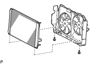
Install the fan shroud with fan motor to the radiator with the 2 bolts.
- Torque:
- 11 N*m (112 kgf*cm, 8 ft.*lbf)
16400
2.INSTALL RADIATOR ASSEMBLY WITH FAN SHROUD AND FAN MOTOR
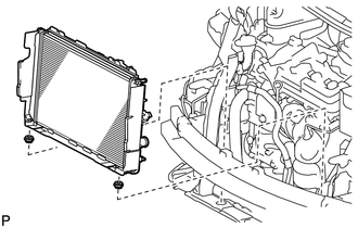
Install the 2 lower radiator support cushions.
Install the radiator with fan shroud and fan motor.
88460
3.INSTALL COOLER CONDENSER ASSEMBLY
88716A
4.INSTALL COOLER REFRIGERANT LIQUID PIPE
88711A
5.INSTALL NO. 1 COOLER REFRIGERANT DISCHARGE HOSE
32921
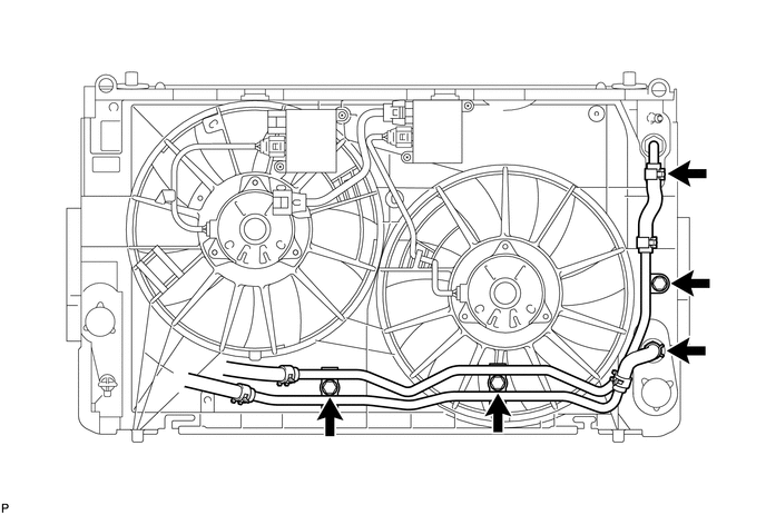
6.CONNECT NO. 1 OIL COOLER INLET TUBE
Connect the oil cooler hose inlet and outlet to the radiator.
Install the tube to the radiator with the 3 bolts.
- Torque:
- 5.5 N*m (56 kgf*cm, 49 in.*lbf)
16572D
7.CONNECT NO. 2 RADIATOR HOSE
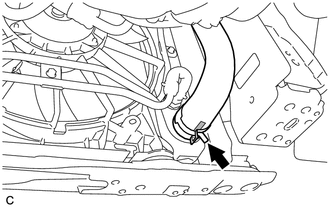
Connect the No. 2 radiator hose to the radiator.
16571C
8.CONNECT NO. 1 RADIATOR HOSE
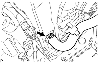
Connect the No. 1 radiator hose to the radiator.
53205
9.INSTALL RADIATOR UPPER SUPPORT SUB-ASSEMBLY
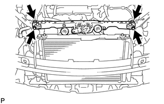
Install the support with wire harness with the 4 bolts.
- Torque:
- 30 N*m (306 kgf*cm, 22 ft.*lbf)
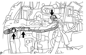
Install the bolt securing the wire ground cable to the radiator support LH side.
- Torque:
- 8.0 N*m (82 kgf*cm, 71 in.*lbf)
Attach the wire harness's clamp to the radiator support LH side.
89257
10.CONNECT COOLING FAN ECU CONNECTORS
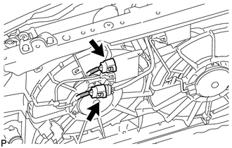
Connect the No. 1 and No. 2 cooling fan ECU connectors.
16268
11.INSTALL NO. 1 WATER BY-PASS PIPE
Install the pipe with the 2 bolts.
- Torque:
- 19 N*m (194 kgf*cm, 14 ft.*lbf)
Connect the No. 1 water by-pass hose to the reservoir, and attach the clamp to the radiator support.
Connect the No. 3 water by-pass hose to the radiator.
Connect the No. 1 water by-pass pipe to the No. 1 radiator hose.
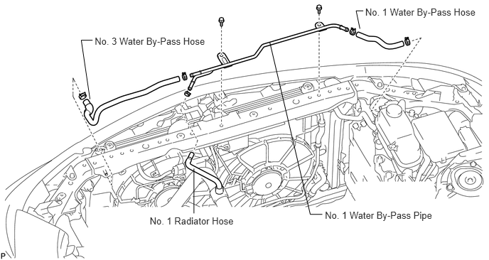
16712
12.INSTALL NO. 2 FAN SHROUD
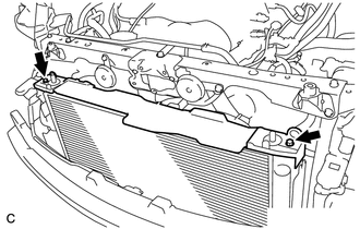
Install the No. 2 fan shroud with the 2 bolts.
- Torque:
- 11 N*m (112 kgf*cm, 8 ft.*lbf)
16533
13.INSTALL RADIATOR SUPPORT UPPER BRACKET
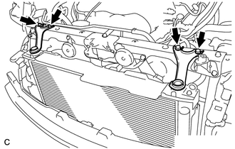
Install the 2 brackets with the 4 bolts.
- Torque:
- 19 N*m (194 kgf*cm, 14 ft.*lbf)
53209B
14.INSTALL HOOD LOCK SUPPORT BRACE SUB-ASSEMBLY
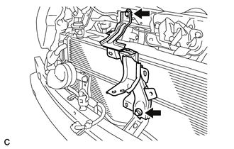
Install the hood lock support brace sub-assembly with the 2 bolts.
- Torque:
- 31 N*m (316 kgf*cm, 23 ft.*lbf)
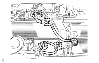
Connect the 3 wire harness clamps to the hood lock support brace sub-assembly.
81175
15.INSTALL HEADLIGHT ASSEMBLY LH
81135
16.INSTALL HEADLIGHT ASSEMBLY RH
- HINT:
-
The installation procedure of the RH side is the same as the LH side.
53510
17.INSTALL HOOD LOCK ASSEMBLY (for LHD)
53510
18.INSTALL HOOD LOCK ASSEMBLY (for RHD)
17751
19.INSTALL NO. 1 AIR CLEANER INLET
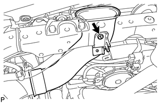
Install the inlet with the clip.
74431
20.INSTALL BATTERY TRAY
28800
21.INSTALL BATTERY
22.CONNECT CABLE TO NEGATIVE BATTERY TERMINAL
Connect the negative (-) cable to the battery negative (-) terminal.
- Torque:
- 5.4 N*m (55 kgf*cm, 48 in.*lbf)
- NOTICE:
-
When disconnecting the cable, some systems need to be initialized after the cable is reconnected (See page General>INTRODUCTION>REPAIR INSTRUCTION>INITIALIZATION).
23.ADD ENGINE COOLANT
24. CHARGE REFRIGERANT
25.WARM UP ENGINE
26.INSPECT FOR COOLANT LEAK
27.CHECK FOR LEAKAGE OF REFRIGERANT
28.ADD AUTOMATIC TRANSAXLE FLUID
51441
29.INSTALL NO. 1 ENGINE UNDER COVER
11209
30.INSTALL V-BANK COVER ASSEMBLY