AIR CONDITIONING FRONT COOLING UNIT INSTALLATION
PROCEDURE

 87130D
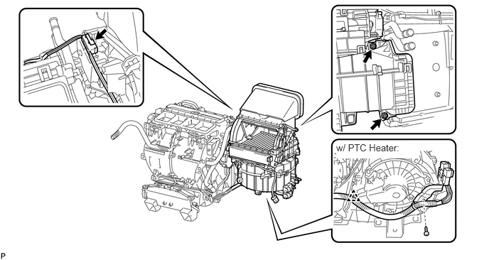
1.INSTALL BLOWER UNIT ASSEMBLY
w/o PTC Heater:
Install the blower unit with the 2 screws.
w/ PTC Heater:
Install the blower unit with the 3 screws.
w/ PTC Heater:
Connect the clamp.
Connect the connector.
87211A
2.INSTALL NO. 2 AIR DUCT
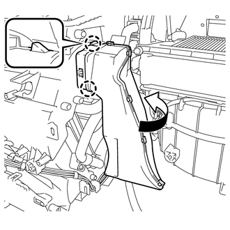
Attach the claw to install the duct.
87211
3.INSTALL NO. 1 AIR DUCT
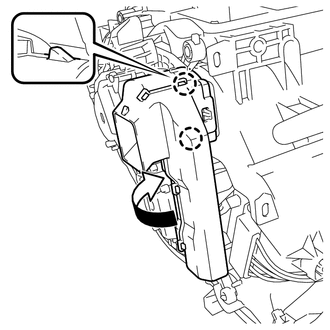
Attach the 2 claws to install the duct.
55950G
4.INSTALL DEFROSTER NOZZLE ASSEMBLY
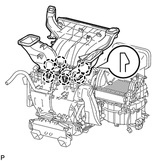
Attach the 4 claws to install the nozzle.
55835A
5.INSTALL HEATER TO REGISTER DUCT CENTER
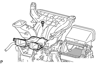
Install the duct with the screw.
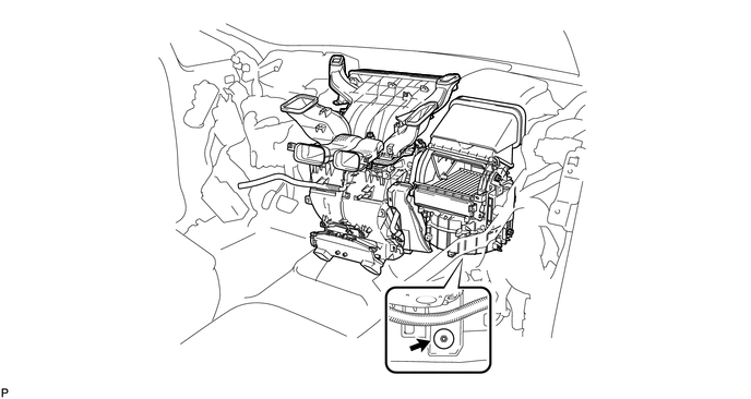
6.INSTALL AIR CONDITIONING UNIT ASSEMBLY
Install the air conditioning unit with the nut.
- Torque:
- 9.8 N*m (100 kgf*cm, 7 ft.*lbf)
55330B
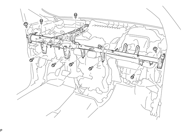
7.INSTALL INSTRUMENT PANEL REINFORCEMENT ASSEMBLY
Install the instrument panel reinforcement with the 11 bolts.
- Torque:
- 9.8 N*m (100 kgf*cm, 7 ft.*lbf)
for bolt A
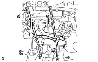
Install the brace with the 3 bolts, 2 screws and 2 nuts.
Attach the clamps and connectors to the wire harness.
Install the ground wire and junction block with the 7 bolts and 4 nuts.
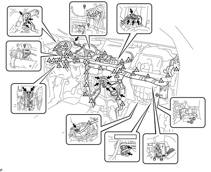
55342A
8.INSTALL NO. 2 INSTRUMENT PANEL TO COWL BRACE
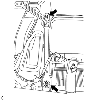
Install the brace with the bolt and nut.
55303B
9.INSTALL LOWER INSTRUMENT PANEL
Install the lower instrument panel (See page Vehicle Interior>INTERIOR PANEL>LOWER INSTRUMENT PANEL>INSTALLATION).
55302A
10.INSTALL UPPER INSTRUMENT PANEL
Install the upper instrument panel (See page Vehicle Interior>INTERIOR PANEL>UPPER INSTRUMENT PANEL>INSTALLATION).
45250
11.INSTALL STEERING COLUMN ASSEMBLY
for LHD:
Install the steering column (See page Steering>STEERING COLUMN>STEERING COLUMN ASSEMBLY(for LHD)>INSTALLATION).
for RHD:
Install the steering column (See page Steering>STEERING COLUMN>STEERING COLUMN ASSEMBLY(for RHD)>INSTALLATION).
87245A
12.CONNECT INLET HEATER WATER HOSE A
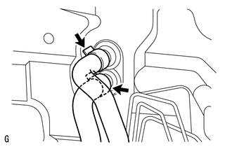
Connect the water hose and attach the clip.
87246
13.CONNECT OUTLET HEATER WATER HOSE
- HINT:
-
Use the same procedures described for the inlet heater water hose A.
88707
14.CONNECT TUBE SUB-ASSEMBLY
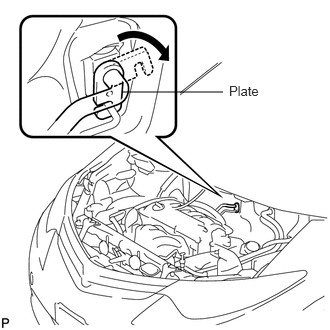
Remove the attached vinyl tape from the pipe.
Sufficiently apply compressor oil to new 2 O-rings and the fitting surface of the suction tube and liquid tube.
- Compressor oil:
ND-OIL 8 or equivalent
Install the 2 O-rings on the suction tube and liquid tube.
Connect the suction tube and liquid tube.
- HINT:
-
After the connection, check that the claw of the piping clamp is engaged.
Install the plate with the bolt.
- Torque:
- 9.8 N*m (100 kgf*cm, 7 ft.*lbf)
15.CONNECT CABLE TO NEGATIVE BATTERY TERMINAL
16.CHECK SRS WARNING LIGHT
Check the SRS warning light (See page Vehicle Interior>SUPPLEMENTAL RESTRAINT SYSTEMS>AIRBAG SYSTEM>DIAGNOSIS SYSTEM).
17.ADD ENGINE COOLANT
for 2AZ-FE: (See page Engine / Hybrid System>2AZ-FE COOLING>COOLANT>REPLACEMENT)
for 2GR-FE: (See page Engine / Hybrid System>2GR-FE COOLING>COOLANT>REPLACEMENT)
18.CHARGE AIR CONDITIONING SYSTEM WITH REFRIGERANT
19.WARM UP ENGINE
20.CHECK FOR ENGINE COOLANT LEAKS
for 2AZ-FE: (See page Engine / Hybrid System>2AZ-FE COOLING>COOLING SYSTEM>ON-VEHICLE INSPECTION)
for 2GR-FE: (See page Engine / Hybrid System>2GR-FE COOLING>COOLING SYSTEM>ON-VEHICLE INSPECTION)
21.INSPECT FOR REFRIGERANT LEAK
22.PERFORM INITIALIZATION
Perform initialization (See page General>INTRODUCTION>REPAIR INSTRUCTION>INITIALIZATION).
- NOTICE:
-
Certain systems need to be initialized after disconnecting and reconnecting the cable from the negative (-) battery terminal.
23.INITIALIZE SERVO MOTOR
Turn the ignition switch off.
Connect the intelligent tester to the DLC3.
Turn the ignition switch to on.
Press the A/C OFF switch.
Turn the intelligent tester on.
Enter the following menus: Body / Air Conditioner / Utility / Servomotor Initialization.
According to the intelligent tester display, select the "Next" switch.
According to the intelligent tester display, select the "Next" switch.
- HINT:
-
During initialization, the AUTO indicator illuminates. When initialization is complete, the indicator turns off.
According to the intelligent tester display, select the exit to finish the initialization.