RC60J MANUAL TRANSMISSION / TRANSAXLE MANUAL TRANSMISSION ASSEMBLY(for 1GD-FTV) INSTALLATION
PROCEDURE

 33146
1.INSTALL EXTENSION HOUSING DUST(MTM) DEFLECTOR
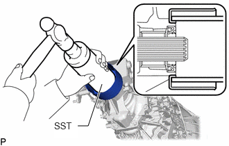
Using SST and hammer, tap in the extension housing dust(MTM) deflector.
- SST
- 09513-36040
2.INSTALL WIRING HARNESS CLAMP BRACKET
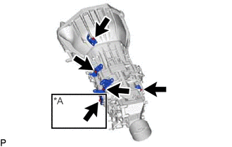
| *A | w/ Sensor |
w/ Sensor:
Install the 5 wiring harness clamp brackets to the manual transmission assembly with the 5 bolts.
- Torque:
- 13 N*m (133 kgf*cm, 10 ft.*lbf)
w/o Sensor:
Install the 4 wiring harness clamp brackets to the manual transmission assembly with the 4 bolts.
- Torque:
- 13 N*m (133 kgf*cm, 10 ft.*lbf)
33827
3.INSTALL NO. 3 TRANSMISSION CONTROL CABLE BRACKET
Install the No. 3 transmission control cable bracket to the manual transmission assembly with the 2 bolts.
- Torque:
- 28 N*m (286 kgf*cm, 21 ft.*lbf)
4.INSTALL MANUAL TRANSMISSION ASSEMBLY
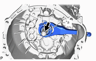
| *a | Contact surface of the bearing |

|
Toyota Genuine Clutch Spline Grease or equivalent |
Apply the clutch spline grease to the spline of the input shaft.
- Grease:
Toyota Genuine Clutch Spline Grease or equivalent
- NOTICE:
-
Make sure that no grease adheres to the contact surface of the bearing.
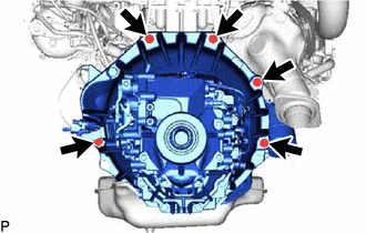
Install the manual transmission assembly with the 5 bolts.
- Torque:
- 71.5 N*m (729 kgf*cm, 53 ft.*lbf)
- HINT:
- Bolt Length
-
50 mm (1.97 in.)
5.CONNECT WIRE HARNESS
Connect the wire harness with the 2 bolts as shown in the illustration.
- Torque:
- for bolt A : 13 N*m (133 kgf*cm, 10 ft.*lbf)
- for bolt B : 19 N*m (194 kgf*cm, 14 ft.*lbf)
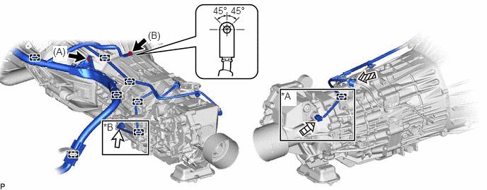
| *A | w/ Stop and Start System | *B | w/ Sensor |
|
|
Bolt | 
|
Transmission Revolution Sensor Connector |

|
Back-up Light Switch Assembly Connector | 
|
Neutral Position Switch Connector |
w/ Sensor:
Connect the transmission revolution sensor connector and attach the wire harness clamp.
w/ Stop and Start System:
Connect the neutral position switch connector and attach the wire harness clamp.
Connect the back-up light switch assembly connector.
Attach the 6 wire harness clamps.
12380
6.INSTALL REAR ENGINE MOUNTING INSULATOR ASSEMBLY
Install the rear engine mounting insulator assembly to the manual transmission assembly with the 4 bolts.
- Torque:
- 48 N*m (489 kgf*cm, 35 ft.*lbf)
57209B
7.INSTALL REAR ENGINE MOUNTING MEMBER SUB-ASSEMBLY
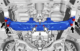
|
|
Bolt |
|
|
Nut |
Install the rear engine mounting member sub-assembly to the body with the 4 bolts.
- Torque:
- 80 N*m (816 kgf*cm, 59 ft.*lbf)
Install the 3 nuts to the rear engine mounting member sub-assembly.
- Torque:
- 48 N*m (489 kgf*cm, 35 ft.*lbf)
w/ Cover:
Install the step plate cover RH.
Click hereEngine / Hybrid System>1GD-FTV (ENGINE MECHANICAL)>ENGINE ASSEMBLY>INSTALLATION
51446B
8.INSTALL NO. 2 ENGINE UNDER COVER BRACKET
Install the No. 2 engine under cover bracket to the frame with the 2 bolts.
- Torque:
- 45 N*m (459 kgf*cm, 33 ft.*lbf)
33820B
9.CONNECT TRANSMISSION CONTROL CABLE ASSEMBLY (for Transmission Assembly Side)
31121
10.INSTALL NO. 1 CLUTCH HOUSING COVER
- HINT:
-
There is no need to remove this unless the No. 1 clutch housing cover is replaced.
Install the No. 1 clutch housing cover to the No. 2 rear end plate.
11.INSTALL NO. 2 REAR END PLATE
Install the No. 2 rear end plate to the engine assembly and manual transmission assembly.
12584
12.INSTALL NO. 4 CYLINDER BLOCK INSULATOR
Install the No. 4 cylinder block insulator to the engine assembly and manual transmission assembly.
33119
13.INSTALL STIFFENER PLATE LH(MTM)
Install the stiffener plate LH(MTM) to the engine assembly and manual transmission assembly with the 4 bolts.
- Torque:
- 71.5 N*m (729 kgf*cm, 53 ft.*lbf)
- HINT:
- Bolt Length
-
35 mm (1.38 in.)
33118
14.INSTALL STIFFENER PLATE RH(MTM)
Install the stiffener plate RH(MTM) to the engine assembly and manual transmission assembly with the 4 bolts.
- Torque:
- 71.5 N*m (729 kgf*cm, 53 ft.*lbf)
- HINT:
- Bolt Length
-
35 mm (1.38 in.)
31470
15.CONNECT CLUTCH RELEASE CYLINDER ASSEMBLY
16.ADD MANUAL TRANSMISSION OIL
28100
17.INSTALL STARTER ASSEMBLY
for 2.0 kW Type:
Click hereEngine / Hybrid System>1GD-FTV (STARTING)>STARTER (for 2.0 kW Type)>INSTALLATION
for 3.0 kW Type:
Click hereEngine / Hybrid System>1GD-FTV (STARTING)>STARTER (for 3.0 kW Type)>INSTALLATION
w/ Stop and Start System:
Click hereEngine / Hybrid System>1GD-FTV (STARTING)>STARTER (w/ Stop And Start System)>INSTALLATION
37100
18.INSTALL PROPELLER SHAFT WITH CENTER BEARING ASSEMBLY
for Standard Roof:
Click hereDrivetrain>DRIVE SHAFT / PROPELLER SHAFT>PROPELLER SHAFT ASSEMBLY (for Standard Roof)>INSTALLATION
for High Roof:
Click hereDrivetrain>DRIVE SHAFT / PROPELLER SHAFT>PROPELLER SHAFT ASSEMBLY (for High Roof)>INSTALLATION
17410
19.INSTALL FRONT EXHAUST PIPE ASSEMBLY
28800
20.CONNECT CABLE TO NEGATIVE BATTERY TERMINAL
33820B
21.ADJUST TRANSMISSION CONTROL CABLE ASSEMBLY
22. INITIALIZATION AFTER RECONNECTING BATTERY TERMINAL
Click hereGeneral>SETUP>WHEN DISCONNECTING OR RECONNECTING BATTERY TERMINAL>WORK PROCEDURE
- HINT:
-
When disconnecting and reconnecting the battery, there is an automatic learning function that completes learning when the respective system is used.
-
Click hereGeneral>SETUP>WHEN DISCONNECTING OR RECONNECTING BATTERY TERMINAL>AUTOMATIC LEARNING CHART