1GD-FTV INTAKE / EXHAUST EXHAUST MANIFOLD W/ TURBOCHARGER REMOVAL
CAUTION / NOTICE / HINT
The necessary procedures (adjustment, calibration, initialization, or registration) that must be performed after parts are removed, installed, or replaced during the turbocharger sub-assembly removal/installation are shown below.
| Replacement Part or Procedure | Necessary Procedures | Effects/Inoperative when not Performed | Link |
|---|---|---|---|
·
Replacement of diesel throttle body assembly ·
Replacement of electric EGR control valve assembly ·
Replacement of turbocharger sub-assembly ·
Replacement of turbocharger sub-assembly or turbocharger variable nozzle motor |
Perform initialization | - | ·
w/ DPF: ( ·
w/ Urea SCR System: ( ·
w/ EGR Cooler: ( ·
w/o EGR Cooler: ( |

- CAUTION:
- ·
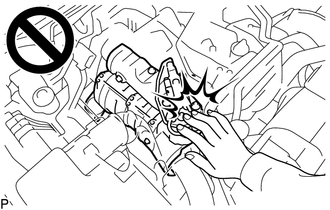
To prevent burns, do not touch the engine, exhaust manifold or other high temperature components while the engine is hot.
·To prevent burns, do not touch the engine, exhaust pipe or other high temperature components while the engine is hot.
PROCEDURE

 12601B
1.REMOVE NO. 1 ENGINE COVER SUB-ASSEMBLY
25051
2.REMOVE EXHAUST MANIFOLD CONVERTER SUB-ASSEMBLY (w/ EGR Cooler)
17167
3.REMOVE NO. 1 EXHAUST MANIFOLD HEAT INSULATOR (w/o EGR Cooler)
17271
4.REMOVE NO. 1 TURBO INSULATOR (w/o EGR Cooler)
5.REMOVE NO. 2 EXHAUST PIPE SUPPORT STAY (w/o EGR Cooler)
6.REMOVE EXHAUST PIPE SUPPORT STAY (w/o EGR Cooler)
17291
7.REMOVE TURBINE OUTLET ELBOW (w/o EGR Cooler)
51406A
8.REMOVE NO. 2 ENGINE UNDER COVER SUB-ASSEMBLY (w/ No. 2 Engine Under Cover Sub-assembly)
52618
9.REMOVE LOWER FRONT BUMPER ABSORBER
51405A
10.REMOVE NO. 1 ENGINE UNDER COVER ASSEMBLY
11.DRAIN ENGINE COOLANT
12.DRAIN ENGINE OIL
17030
13.REMOVE AIR HOSE ASSEMBLY
25761B
14.DISCONNECT NO. 1 VACUUM TRANSMITTING HOSE
17303T
15.REMOVE AIR PIPE SUB-ASSEMBLY
16571C
16.REMOVE NO. 1 RADIATOR HOSE
44360
17.DISCONNECT VANE PUMP OIL RESERVOIR ASSEMBLY
53106B
18.REMOVE RADIATOR COVER SUB-ASSEMBLY
17751
19.REMOVE NO. 1 AIR CLEANER INLET
16470
20.REMOVE RADIATOR RESERVOIR
16711
21.REMOVE FAN SHROUD
17705
22.REMOVE AIR CLEANER CAP SUB-ASSEMBLY WITH AIR CLEANER HOSE
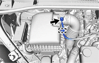
Disconnect the mass air flow meter sub-assembly connector and detach the harness clamp.
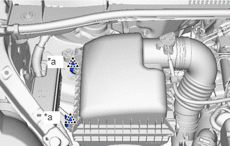
| *a | Air Cleaner Cap Clamp |
Detach the 2 air cleaner cap clamps.
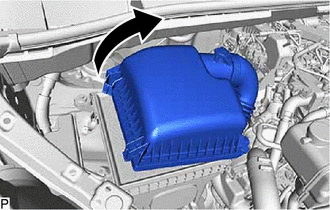
Detach the 2 guides to disconnect the air cleaner cap sub-assembly from the air cleaner case sub-assembly.
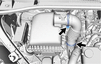
Loosen the hose clamp and remove the air cleaner cap sub-assembly with air cleaner hose.
17801
23.REMOVE AIR CLEANER FILTER ELEMENT SUB-ASSEMBLY
Remove the air cleaner element sub-assembly from the air cleaner case.
17701
24.REMOVE AIR CLEANER CASE SUB-ASSEMBLY
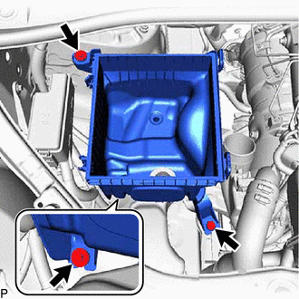
Remove the 3 bolts and air cleaner case sub-assembly.
25.REMOVE WATER HOSE SUB-ASSEMBLY (w/ Viscous Heater)
87120G
26.REMOVE VISCOUS HEATER WITH MAGNET CLUTCH ASSEMBLY (w/ Viscous Heater)
16279
27.REMOVE NO. 3 WATER BY-PASS PIPE
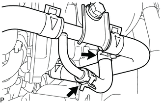
for Cold Area Specification Vehicles:
Slide the 2 hose clips and remove the water hose from the compressor inlet elbow and No. 3 water by-pass pipe.
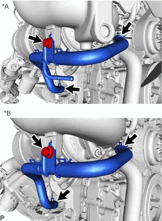
| *A | for Cold Area Specification Vehicles |
| *B | except Cold Area Specification Vehicles |
Slide the 2 hose clips and disconnect the 2 water hoses from the oil cooler assembly and No. 2 water by-pass pipe.
Remove the bolt and No. 3 water by-pass pipe.
12229
28.REMOVE PCV PIPE (for Cold Area Specification Vehicles)
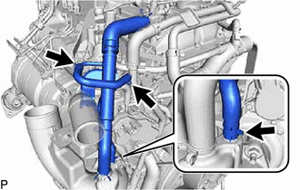
Slide the 2 hose clips and disconnect the No. 20 water by-pass hose from the PCV pipe and No. 3 water by-pass pipe.
Slide the hose clip and disconnect the No. 19 water by-pass hose from the compressor inlet elbow.
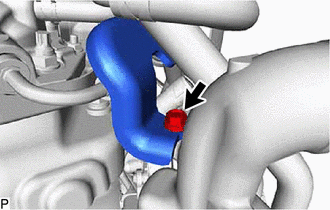
Remove the bolt and disconnect the PCV pipe from the compression outlet elbow.
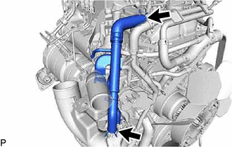
Slide the 2 hose clips and remove the PCV pipe.
12261
29.REMOVE PCV HOSE (except Cold Area Specification Vehicles)
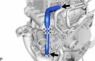
Slide the 2 hose clips, detach the clamp and remove the PCV hose.
30.REMOVE WATER BY-PASS HOSE (for Water Cooled Compressor Housing Turbochager)
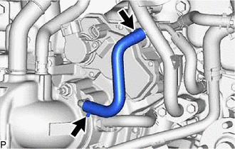
Slide the 2 hose clips and disconnect the No. 21 water by-pass hose from the turbocharger sub-assembly and No. 1 water by-pass pipe.
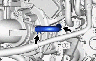
Slide the 2 hose clips and disconnect the No. 4 turbo water hose from the turbocharger sub-assembly and No. 1 turbo water pipe sub-assembly.
16268
31.REMOVE NO. 1 WATER BY-PASS PIPE
16284
32.DISCONNECT TURBO WATER HOSE
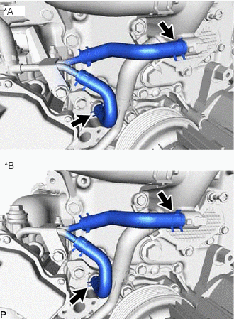
| *A | w/ DPF |
| *B | w/o DPF |
Slide the 2 hose clips and disconnect the No. 1 turbo water hose and No. 2 turbo water hose from the water outlet sub-assembly and water pump assembly.
33.DISCONNECT BRACKET OIL COOLER TUBE BRACKET AND WIRE HARNESS CLAMP BRACKET (for Automatic Transmission)
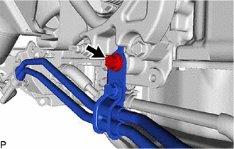
Remove the bolt and disconnect the oil cooler tube bracket.
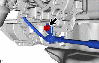
Remove the bolt and disconnect the wire harness.
34.DISCONNECT WIRE HARNESS CLAMP BRACKET (for Manual Transmission)
Remove the bolt and disconnect the wire harness.
87101
35.REMOVE NO. 1 VISCOUS HEATER BRACKET SUB-ASSEMBLY (for Cold Area Specification Vehicles)
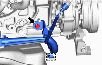
Remove the bolt, detach the clamp and disconnect the wire harness.
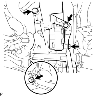
Remove the 4 bolts and the No. 1 viscous heater bracket sub-assembly.
17293
36.REMOVE TURBOCHARGER STAY
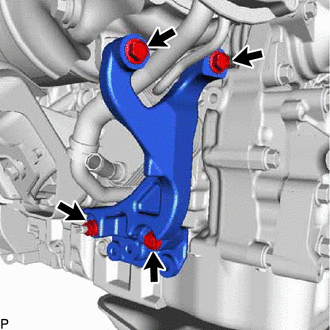
Remove the 3 bolts, nut and the turbocharger stay.
15474
37.REMOVE TURBO OIL OUTLET PIPE
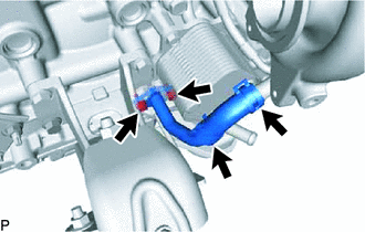
Slide the 2 hose clips and disconnect the turbo oil outlet hose from the turbo oil outlet pipe.
Remove the 2 bolts and turbo oil outlet pipe and gasket.
15407
38.REMOVE TURBO OIL INLET PIPE SUB-ASSEMBLY
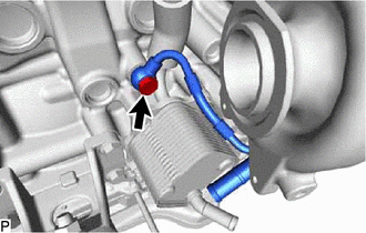
Remove the union bolt and gasket.
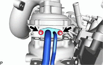
Remove the 2 nuts and the turbo oil inlet pipe sub-assembly.
- NOTICE:
-
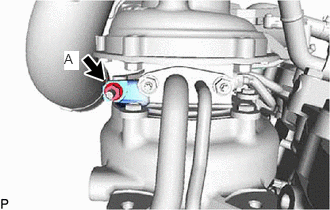 0.667,0.531 0.823,0.729 0.156,0.198 10 true A
-
Do not loosen the nut labeled A.
Remove the gasket.
17201
39.REMOVE TURBOCHARGER SUB-ASSEMBLY
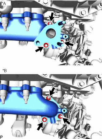
| *A | w/ DPF |
| *B | w/o DPF |
Remove the 3 nuts and turbocharger sub-assembly.
Remove the gasket from the exhaust manifold.
25601
40.REMOVE NO. 1 EGR PIPE SUB-ASSEMBLY (w/ EGR System)
25601
41.REMOVE EGR PIPE WITH COOLER SUB-ASSEMBLY (for Laminated EGR Pre-cooler)
25617
42.REMOVE EGR HOLE COVER PLATE (w/o EGR System)
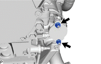
Remove the 2 nuts, EGR hole cover plate and gasket.
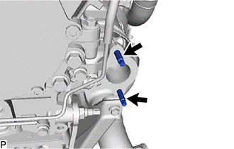
Using an E8 "TORX" socket wrench, remove the 2 stud bolts shown in the illustration.
17141
43.REMOVE EXHAUST MANIFOLD
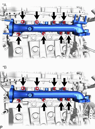
| *A | w/ DPF |
| *B | w/o DPF |
Remove the 8 nuts, 8 plate washers, 8 collars and exhaust manifold.
Remove the gasket.
16027
44.REMOVE NO. 1 TURBO WATER PIPE SUB-ASSEMBLY
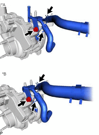
| *A | w/ DPF |
| *B | w/o DPF |
except Water Cooled Compressor Housing Turbochager:
Slide the 2 hose clips and disconnect the No. 1 turbo water hose and No. 2 turbo water hose from the turbo water pipe sub-assembly.
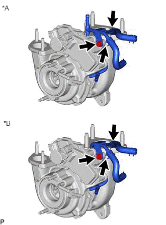
| *A | w/ DPF |
| *B | w/o DPF |
for Water Cooled Compressor Housing Turbochager:
Slide the 2 hose clips and disconnect the No. 1 turbo water hose and No. 2 turbo water hose from the turbo water pipe sub-assembly.
Remove the bolt.
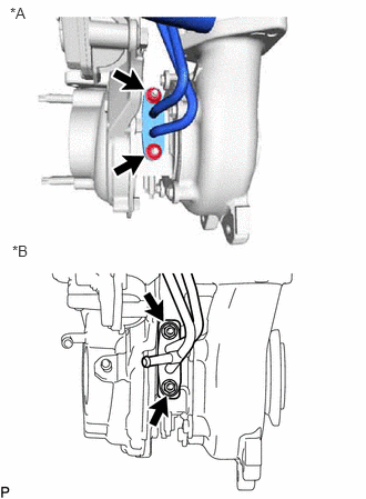
| *A | except Water Cooled Compressor Housing Turbochager |
| *B | for Water Cooled Compressor Housing Turbochager |
Remove the 2 nuts, turbo water pipe sub-assembly and gasket.
17274
45.REMOVE COMPRESSOR INLET ELBOW
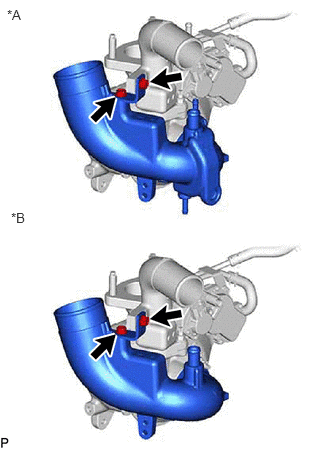
| *A | for Cold Area Specification Vehicles |
| *B | except Cold Area Specification Vehicles |
Remove the 2 bolts and compressor inlet elbow stay.
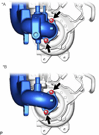
| *A | for Cold Area Specification Vehicles |
| *B | except Cold Area Specification Vehicles |
except Water Cooled Compressor Housing Turbochager:
Remove the 2 nuts and compressor inlet elbow from turbocharger sub-assembly.
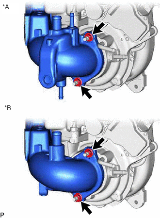
| *A | for Cold Area Specification Vehicles |
| *B | except Cold Area Specification Vehicles |
for Water Cooled Compressor Housing Turbochager:
Remove the 2 nuts and compressor inlet elbow from turbocharger sub-assembly.
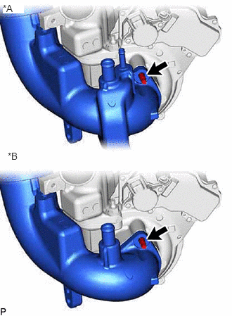
| *A | for Cold Area Specification Vehicles |
| *B | except Cold Area Specification Vehicles |
except Water Cooled Compressor Housing Turbochager:
Using an E8 "TORX" socket wrench, remove the stud bolt shown in the illustration together with the compressor inlet elbow and gasket.
for Water Cooled Compressor Housing Turbochager:
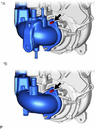
| *A | for Cold Area Specification Vehicles |
| *B | except Cold Area Specification Vehicles |
Using an E8 "TORX" socket wrench, remove the stud bolt shown in the illustration together with the compressor inlet elbow.
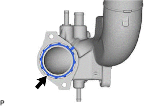
Remove the gasket from the compressor inlet elbow.
17275
46.REMOVE COMPRESSOR OUTLET ELBOW
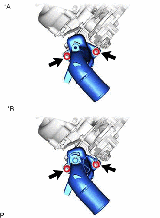
| *A | for Cold Area Specification Vehicles |
| *B | except Cold Area Specification Vehicles |
Remove the 2 nuts and compressor outlet elbow.
Remove the gasket.
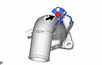
except Cold Area Specification Vehicles:
Remove the bolt and hose clamp.
47.REMOVE STUD BOLT
- NOTICE:
-
If a stud bolt is deformed or its threads are damaged, replace it.
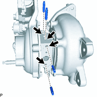
Using an E5 "TORX" socket wrench, remove the 4 stud bolts shown in the illustration.
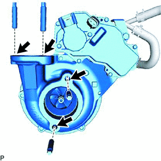
Using an E8 "TORX" socket wrench, remove the 4 stud bolts shown in the illustration.
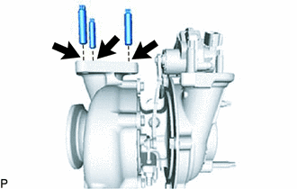
Using an E10 "TORX" socket wrench, remove the 3 stud bolts shown in the illustration.