HEATING / AIR CONDITIONING FRONT AIR CONDITIONING UNIT(for RHD) INSTALLATION
CAUTION / NOTICE / HINT
- HINT:
-
A bolt without a torque specification is shown in the standard bolt chart.
-
Click hereGeneral>SPECIFICATIONS>STANDARD BOLT>SPECIFIED TORQUE FOR STANDARD BOLTS
PROCEDURE

 88539D
1.INSTALL COOLER UNIT DRAIN PIPE
- HINT:
-
Perform this procedure only when removal/installation of the cooler unit drain pipe is necessary.
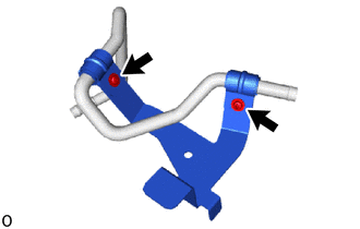
Install the piping clamp with 2 screws.
88539C
2.INSTALL NO. 2 COOLER UNIT DRAIN HOSE
- HINT:
-
Perform this procedure only when removal/installation of the No. 2 cooler unit drain hose is necessary.
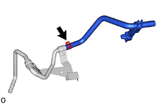
Install the No. 2 cooler unit drain hose to cooler unit drain pipe.
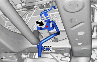
Temporarily install the cooler unit drain pipe with No. 2 cooler unit drain hose.
Install the cooler unit drain pipe with No. 2 cooler unit drain hose with the bolt and attach the clamp.
88539
3.INSTALL NO. 1 COOLER UNIT DRAIN HOSE
- NOTICE:
- Perform this procedure only when removal/installation of the No. 1 cooler unit drain hose is necessary.
-
After removing the No. 1 cooler unit drain hose, replace it with a new one to prevent water from entering.
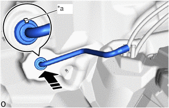
| *a | Marking |

|
Install in this Direction |
Install the No. 1 cooler unit drain hose.
- NOTICE:
-
Install the No. 1 cooler unit drain hose with its paint mark facing upward.
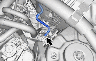
Connect the No. 1 cooler unit drain hose to cooler unit drain pipe.
23300
4.INSTALL FUEL FILTER ASSEMBLY (for 1GD-FTV)
- HINT:
-
Perform this procedure only when removal/installation of the No. 1 cooler unit drain hose and No. 2 cooler unit drain hose is necessary.
Click hereEngine / Hybrid System>1GD-FTV (FUEL)>FUEL FILTER>REPLACEMENT
51405A
5.INSTALL NO. 1 ENGINE UNDER COVER SUB-ASSEMBLY
- HINT:
-
Perform this procedure only when removal/installation of the No. 1 cooler unit drain hose and No. 2 cooler unit drain hose is necessary.
for 7GR-FKS:
Click hereEngine / Hybrid System>7GR-FKS (ENGINE MECHANICAL)>ENGINE ASSEMBLY>INSTALLATION
for 1GD-FTV:
Click hereEngine / Hybrid System>1GD-FTV (ENGINE MECHANICAL)>ENGINE ASSEMBLY>INSTALLATION
52618
6.INSTALL LOWER FRONT BUMPER ABSORBER
- HINT:
-
Perform this procedure only when removal/installation of the No. 1 cooler unit drain hose and No. 2 cooler unit drain hose is necessary.
for 7GR-FKS:
Click hereEngine / Hybrid System>7GR-FKS (ENGINE MECHANICAL)>ENGINE ASSEMBLY>INSTALLATION
for 1GD-FTV:
Click hereEngine / Hybrid System>1GD-FTV (ENGINE MECHANICAL)>ENGINE ASSEMBLY>INSTALLATION
51406A
7.INSTALL NO. 2 ENGINE UNDER COVER SUB-ASSEMBLY (w/ No. 2 Engine Under Cover Sub-assembly)
- HINT:
-
Perform this procedure only when removal/installation of the No. 1 cooler unit drain hose and No. 2 cooler unit drain hose is necessary.
for 7GR-FKS:
Click hereEngine / Hybrid System>7GR-FKS (ENGINE MECHANICAL)>ENGINE ASSEMBLY>INSTALLATION
for 1GD-FTV:
Click hereEngine / Hybrid System>1GD-FTV (ENGINE MECHANICAL)>ENGINE ASSEMBLY>INSTALLATION
8.INSTALL AIR CONDITIONER UNIT ASSEMBLY
- NOTICE:
- ·
Be sure to support the air conditioning unit assembly when installing it because failure to do so may cause the bracket of the air conditioning unit assembly to break.
·When installing the air conditioning unit assembly, eliminate static electricity by touching the vehicle body to prevent the components from being damaged.
·Be careful not to damage the internal components of the instrument panel reinforcement assembly and air conditioning unit assembly on the glass etc. Only perform installation after first taking the appropriate actions.
·Do not allow the air conditioning unit assembly to strike the airbag ECU assembly. Doing so may damage the heater case, causing water leaks.
Temporarily install the air conditioner unit assembly to the instrument panel reinforcement assembly with the 4 bolts.
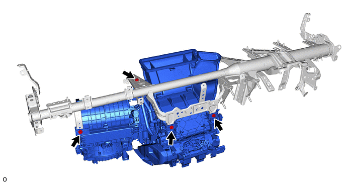
- NOTICE:
- When carrying the air conditioning unit assembly, hold the bottom of the assembly. Do not hold the following parts.
- ·
Do not hold the air conditioning harness assembly. Otherwise, static electricity from the technician may damage the air conditioning harness assembly.
·Do not hold the heater core or pipe of the heater radiator unit sub-assembly. Otherwise, the pipe may detach, the clamp may be damaged, or the crimped areas of the heater core and pipe of the heater radiator unit sub-assembly may be damaged, causing coolant to leak.
·Do not hold the air conditioning radiator damper servo sub-assembly, blower damper servo sub-assembly or link. Otherwise, the servo motor may become misaligned, causing abnormal operation noise, temperature control defects, or air leaks due to sealing defects in the doors.
·Do not hold the door. Doing so may cause air leaks due to closing defects resulting from excessive opening/closing. Also, keep the door free from oil and grease.
9.INSTALL INSTRUMENT PANEL REINFORCEMENT ASSEMBLY WITH AIR CONDITIONER UNIT ASSEMBLY
- NOTICE:
- ·
Be sure to support the air conditioning unit assembly when installing it because failure to do so may cause the bracket of the air conditioning unit assembly to break.
·When installing the air conditioning unit assembly, eliminate static electricity by touching the vehicle body to prevent the components from being damaged.
·Be careful not to damage the internal components of the instrument panel reinforcement assembly with air conditioning unit assembly on the glass etc. Only perform installation after first taking the appropriate actions.
Temporarily install the instrument panel reinforcement assembly with air conditioner unit assembly.
- NOTICE:
- ·
Do not allow the heater radiator unit sub-assembly heater pipe or cooler expansion valve to strike the body.
·Make sure that both parts are securely installed to the guide.
for Automatic Transmission:
Install the instrument panel reinforcement assembly with the 8 bolts.
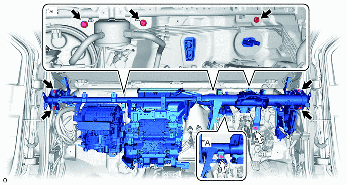
| *A | for Manual Transmission | - | - |
| *a | Engine Room Side | - | - |

|
Bolt A | 
|
Bolt B |
- Torque:
- Bolt A : 25 N*m (255 kgf*cm, 18 ft.*lbf)
- Bolt B : 23.6 N*m (241 kgf*cm, 17 ft.*lbf)
for Manual Transmission:
Install the instrument panel reinforcement assembly with the 9 bolts.
- Torque:
- Bolt A : 25 N*m (255 kgf*cm, 18 ft.*lbf)
- Bolt B : 23.6 N*m (241 kgf*cm, 17 ft.*lbf)
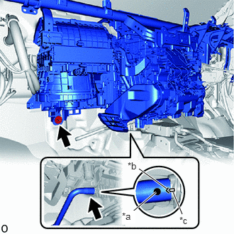
| *a | Standard Position |
| *b | Hose Notch |
| *c | Rib |
Align the standard position, install the drain cooler hose.
Tighten the nut.
88650N
10.INSTALL AIR CONDITIONING AMPLIFIER ASSEMBLY
55306A
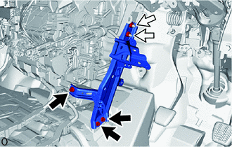
11.INSTALL NO. 1 INSTRUMENT PANEL BRACE SUB-ASSEMBLY
|
|
Bolt |
|
|
Nut |
Install the No. 1 instrument panel brace sub-assembly with the 3 bolts and 2 nuts.
- Torque:
- Bolt: : 20 N*m (204 kgf*cm, 15 ft.*lbf)
- Nut: : 18 N*m (184 kgf*cm, 13 ft.*lbf)
55307C
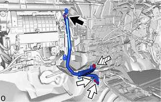
12.INSTALL NO. 2 INSTRUMENT PANEL BRACE SUB-ASSEMBLY
|
|
Nut |
|
|
Bolt |

|
Screw |
Install the No. 2 instrument panel brace sub-assembly with the 2 bolts.
- Torque:
- 20 N*m (204 kgf*cm, 15 ft.*lbf)
Install the nut and screw.
- Torque:
- 18 N*m (184 kgf*cm, 13 ft.*lbf)
13.INSTALL AIR CONDITIONER UNIT ASSEMBLY
Tighten the 4 bolts in the order shown in the illustration.
- Torque:
- Bolt A : 10 N*m (102 kgf*cm, 7 ft.*lbf)
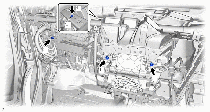
| *a | Bolt(A) | - | - |
87201A
14.INSTALL AIR DUCT SUB-ASSEMBLY
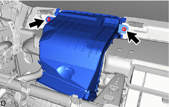
Temporarily install the air duct sub-assembly.
Tighten the 2 nuts.
55950G
15.INSTALL DEFROSTER NOZZLE ASSEMBLY
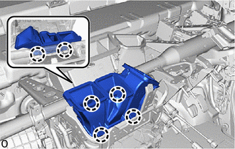
Attach the claw to install the defroster nozzle assembly.
82141
16.INSTALL INSTRUMENT PANEL WIRE
Connect each connector and attach each clamp and install the instrument panel wire.
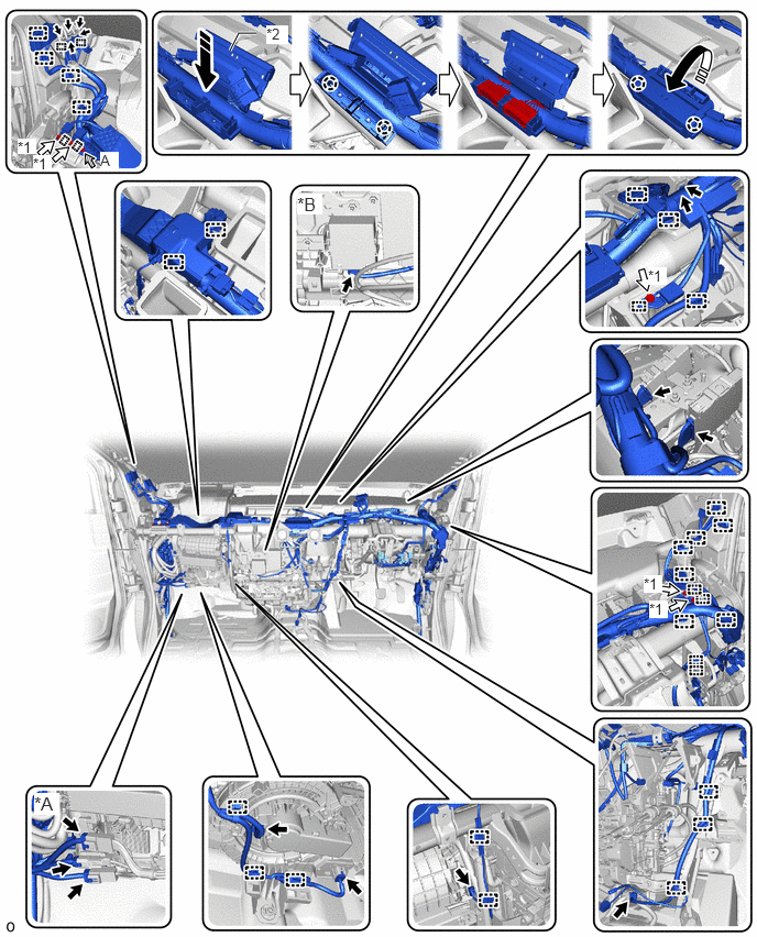
| *A | w/ PTC Heater | *B | w/ VFC ECU |
| *1 | Ground Wire | *2 | Protector Cover |
|
|
Connector |
|
Bolt |
|
|
Nut |
|
Install in this Direction |
Install the nut.
- Torque:
- 12.5 N*m (127 kgf*cm, 9 ft.*lbf)
Attach the claw and install the protector cover together with the instrument panel wire.
Attach the claw and close protector cover.
Install each bolt and each ground wire.
- Torque:
- 10 N*m (102 kgf*cm, 7 ft.*lbf)
58193G
17.INSTALL NO. 3 FRONT FLOOR FOOTREST
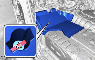
Attach the clip to install the No. 3 front floor footrest.
58510D
18.INSTALL FRONT FLOOR CARPET ASSEMBLY
w/ Console Box:
Install the front floor carpet assembly to the original position as shown in the illustration.
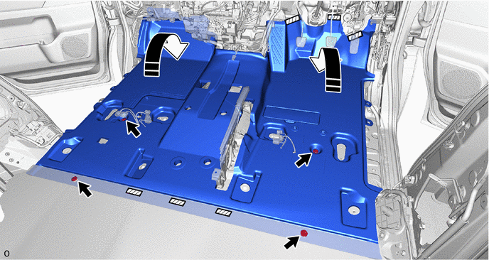
|
|
Install in this Direction | 
|
Fastener |
Attach each fastener.
Install the 4 clips.
w/o Console Box:
Install the front floor carpet assembly to the original position as shown in the illustration.
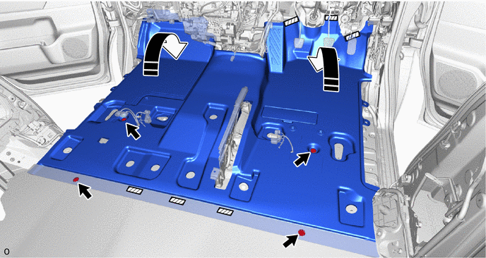
|
|
Install in this Direction |
|
Fastener |
Attach each fastener.
Install the 4 clips.
62510M
19.INSTALL QUARTER TRIM PANEL ASSEMBLY RH (for 4 Door)
- HINT:
-
Use the same procedure described for the LH side.
-
Click hereVehicle Interior>INTERIOR PANELS / TRIM>ROOF HEADLINING (for Full-trim)>INSTALLATION
62610K
20.INSTALL SIDE TRIM BOARD ASSEMBLY RH (for High Roof, for Full-trim)
- HINT:
-
Use the same procedure described for the LH side.
-
Click hereVehicle Interior>INTERIOR PANELS / TRIM>ROOF HEADLINING (for Full-trim)>INSTALLATION
62630L
21.INSTALL REAR QUARTER TRIM BOARD ASSEMBLY RH (for 4 Door)
- HINT:
-
Use the same procedure described for the LH side.
-
Click hereVehicle Interior>INTERIOR PANELS / TRIM>ROOF HEADLINING (for Full-trim)>INSTALLATION
73570B
22.INSTALL REAR SEAT OUTER BELT ASSEMBLY (FLOOR ANCHOR) (for 4 Door, w/ Seat Belt)
- HINT:
-
Use the same procedure described for the LH side.
-
Click hereVehicle Interior>SEAT BELT>REAR SEAT OUTER BELT ASSEMBLY (for Full-trim)>INSTALLATION
67935
23.INSTALL BACK DOOR SCUFF PLATE (for 4 Door)
62413A
24.INSTALL LOWER CENTER PILLAR GARNISH RH (for 5 Door)
67917C
25.INSTALL REAR DOOR SCUFF PLATE RH (for 5 Door)
except Wagon:
Click hereVehicle Interior>INTERIOR PANELS / TRIM>ROOF HEADLINING (for Semi-trim)>INSTALLATION
for Wagon:
Click hereVehicle Interior>INTERIOR PANELS / TRIM>ROOF HEADLINING (for Wagon)>INSTALLATION
62414A
26.INSTALL LOWER CENTER PILLAR GARNISH LH
- HINT:
-
Use the same procedure described for the RH side.
-
Click hereVehicle Interior>INTERIOR PANELS / TRIM>ROOF HEADLINING (for Full-trim)>INSTALLATION
74680
27.INSTALL PILLAR ASSIST GRIP ASSEMBLY B (w/ Assist Grip)
74617A
28.INSTALL ASSIST GRIP PLUG (w/ Assist Grip)
- HINT:
-
Use the same procedure for both assist grip plugs.
-
Click hereVehicle Interior>INTERIOR PANELS / TRIM>ROOF HEADLINING (for Full-trim)>INSTALLATION
67918D
29.INSTALL REAR DOOR SCUFF PLATE LH
- HINT:
-
Use the same procedure described for the RH side.
for Wagon:
Click hereVehicle Interior>INTERIOR PANELS / TRIM>ROOF HEADLINING (for Wagon)>INSTALLATION
for Semi-trim:
Click hereVehicle Interior>INTERIOR PANELS / TRIM>ROOF HEADLINING (for Semi-trim)>INSTALLATION
for Full-trim:
Click hereVehicle Interior>INTERIOR PANELS / TRIM>ROOF HEADLINING (for Full-trim)>INSTALLATION
74733
30.INSTALL NO. 1 HAND GRIP COVER (w/ Hand Rail)
74708
31.INSTALL NO. 2 HAND GRIP FRAME SUB-ASSEMBLY (w/ Hand Rail)
73220
32.INSTALL FRONT SEAT OUTER BELT ASSEMBLY LH (FLOOR ANCHOR)
for Wagon:
Click hereVehicle Interior>SEAT BELT>FRONT SEAT OUTER BELT ASSEMBLY (for Wagon)>INSTALLATION
for Semi-trim:
Click hereVehicle Interior>SEAT BELT>FRONT SEAT OUTER BELT ASSEMBLY (for Semi-trim)>INSTALLATION
for Full-trim:
Click hereVehicle Interior>SEAT BELT>FRONT SEAT OUTER BELT ASSEMBLY (for Full-trim)>INSTALLATION
73210
33.INSTALL FRONT SEAT OUTER BELT ASSEMBLY RH (FLOOR ANCHOR)
- HINT:
-
Use the same procedure described for the LH side.
34.INSTALL OUTER LAP BELT ANCHOR COVER
for Wagon:
Click hereVehicle Interior>SEAT BELT>FRONT SEAT OUTER BELT ASSEMBLY (for Wagon)>INSTALLATION
for Semi-trim:
Click hereVehicle Interior>SEAT BELT>FRONT SEAT OUTER BELT ASSEMBLY (for Semi-trim)>INSTALLATION
for Full-trim:
Click hereVehicle Interior>SEAT BELT>FRONT SEAT OUTER BELT ASSEMBLY (for Full-trim)>INSTALLATION
35.INSTALL TRANSMISSION INSTRUMENT PANEL SHIFT ASSEMBLY (for Automatic Transmission)
33530K
36.INSTALL SHIFT LEVER ASSEMBLY (for Manual Transmission)
45250
37.INSTALL STEERING COLUMN ASSEMBLY
87212F
38.INSTALL REAR NO. 2 AIR DUCT (w/ Rear Foot Duct)
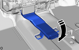
|
|
Install in this Direction |
Install the rear No. 2 air duct as shown in the illustration.
87212G
39.INSTALL REAR NO. 3 AIR DUCT (w/ Rear Foot Duct)
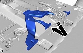
|
|
Install in this Direction |
Install the rear No. 3 air duct as shown in the illustration.
87211
40.INSTALL NO. 1 AIR DUCT
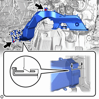
Attach the claw to install a new No. 1 air duct.
Install the 2 bolts.
- NOTICE:
- ·
When removing, do not crack or deform the lower heater case of the air conditioning radiator assembly.
·If the No. 1 air duct is reused, it may fall off or abnormal noise may occur. Therefore, make sure to replace with a new one.
41.INSTALL INSTRUMENT PANEL JUNCTION BLOCK ASSEMBLY WITH MAIN BODY ECU
55301
42.INSTALL INSTRUMENT PANEL SUB-ASSEMBLY
43.INSTALL FRONT SEAT ASSEMBLY
for Power Seat Type:
Click hereVehicle Interior>SEAT>FRONT SEAT ASSEMBLY (for Power Seat)>INSTALLATION
for Separate Seat:
Click hereVehicle Interior>SEAT>FRONT SEAT ASSEMBLY (for Separate Seat Type)>INSTALLATION
for Fixed Bench Seat:
Click hereVehicle Interior>SEAT>FRONT SEAT ASSEMBLY (for Fixed Bench Seat Type)>INSTALLATION
for Sliding Bench Seat:
Click hereVehicle Interior>SEAT>FRONT SEAT ASSEMBLY (for Sliding Bench Seat Type)>INSTALLATION
87128
44.CONNECT HEATER GROMMET
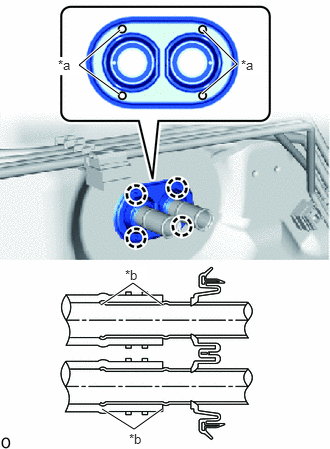
| *a | Marked Part |
| *b | Spool |
Press the marked parts to attach the claw and install the heater grommet.
- NOTICE:
- ·
Push the heater grommet lip seal until it passes over the spools of the heater pipes as shown in the illustration.
·Make sure that the lip portion of the heater grommet does not sit on top of the spools of the heater pipes.
·Make sure that there is no gap between the heater grommet and dash panel.
·Securely fit the heater grommet onto the dash panel. Otherwise, water may enter from the engine room or cause increased noise, vibration or harshness.
87245A
45.CONNECT HEATER WATER HOSE INLET A (for 1GD-FTV)
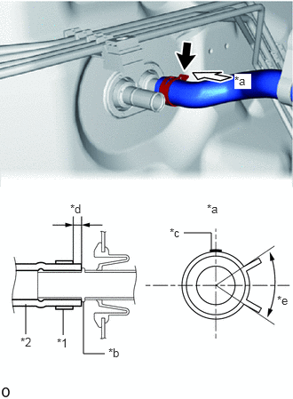
| *1 | Hose Clip |
| *2 | Heater Water Hose Inlet A |
| *a | View A |
| *b | Stopper |
| *c | Marking (White or Brown) |
| *d | Hose Clip Installation Range (7.5 mm (0.295 in.)) |
| *e | Clip Installation Angle (60°) |
Connect the heater water hose inlet A with the marking facing left and attach the clip within the area shown in the illustration.
- NOTICE:
- ·
Do not apply excessive force to the heater water hose inlet A.
·Make sure the heater water hose inlet A is securely inserted to the stopper. However, if the end of the heater water hose outlet A is cut diagonally, it is acceptable for the entire circumference of the tip to not contact the stopper.
·Connect the heater water hose inlet A so that its marking faces the top of the vehicle.
Make sure to install the hose clip within the range shown in the illustration.
- NOTICE:
-
Make sure that the hose clamps do not contact each other.
87246A
46.CONNECT HEATER WATER HOSE OUTLET A (for 1GD-FTV)
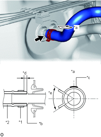
| *1 | Hose Clip |
| *2 | Heater Water Hose Outlet A |
| *a | View A |
| *b | Stopper |
| *c | Marking (Brown) |
| *d | Hose Clip Installation Range (7.5 mm (0.295 in.)) |
| *e | Clip Installation Angle (60°) |
Connect the heater water hose outlet A with the marking facing left and attach the clip within the area shown in the illustration.
- NOTICE:
- ·
Do not apply excessive force to the heater water hose inlet A.
·Make sure the heater water hose outlet A is securely inserted to the stopper. However, if the end of the heater water hose inlet A is cut diagonally, it is acceptable for the entire circumference of the tip to not contact the stopper.
·Connect the heater water hose outlet A so that its marking faces the top of the vehicle.
Make sure to install the hose clip within the range shown in the illustration.
- NOTICE:
-
Make sure that the hose clamps do not contact each other.
87246A
47.CONNECT HEATER WATER HOSE OUTLET A (for 7GR-FKS)
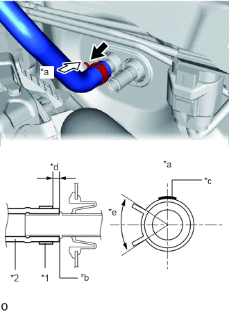
| *1 | Hose Clip |
| *2 | Heater Water Hose Outlet A |
| *a | View A |
| *b | Stopper |
| *c | Marking (White or Pink) |
| *d | Hose Clip Installation Range (7.5 mm (0.295 in.)) |
| *e | Clip Installation Angle (60°) |
Connect the heater water hose outlet A with the marking facing left and attach the clip within the area shown in the illustration.
- NOTICE:
- ·
Do not apply excessive force to the heater water hose outlet A.
·Make sure the heater water hose outlet A is securely inserted to the stopper. However, if the end of the heater water hose outlet A is cut diagonally, it is acceptable for the entire circumference of the tip to not contact the stopper.
·Connect the heater water hose outlet A so that its marking faces the top of the vehicle.
Make sure to install the hose clip within the range shown in the illustration.
- NOTICE:
-
Make sure that the hose clamps do not contact each other.
87245A
48.CONNECT HEATER WATER HOSE INLET A (for 7GR-FKS)
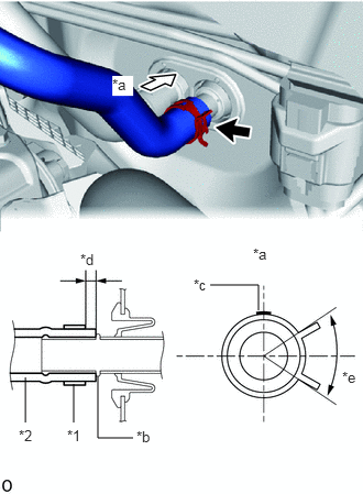
| *1 | Hose Clip |
| *2 | Heater Water Hose Inlet A |
| *a | View A |
| *b | Stopper |
| *c | Marking (Pink) |
| *d | Hose Clip Installation Range (7.5 mm (0.295 in.)) |
| *e | Clip Installation Angle (60°) |
Connect the heater water hose intlet A with the marking facing left and attach the clip within the area shown in the illustration.
- NOTICE:
- ·
Do not apply excessive force to the heater water hose inlet A.
·Make sure the heater water hose inlet A is securely inserted to the stopper. However, if the end of the heater water hose inlet A is cut diagonally, it is acceptable for the entire circumference of the tip to not contact the stopper.
·Connect the heater water hose inlet A so that its marking faces the top of the vehicle.
Make sure to install the hose clip within the range shown in the illustration.
- NOTICE:
-
Make sure that the hose clamps do not contact each other.
88710C
49.CONNECT AIR CONDITIONING TUBE ASSEMBLY (w/ Sub-cool Accelerator)
Remove the vinyl tape wrapped around the connection of the air conditioning tube assembly.
Sufficiently apply compressor oil to a new O-ring and the fitting surface of the air conditioning tube assembly.
- Compressor oil:
ND-OIL 8 or equivalent
Install the O-ring to the air conditioning tube assembly.
- NOTICE:
-
Keep the O-rings and O-ring fitting surfaces free of foreign matter.
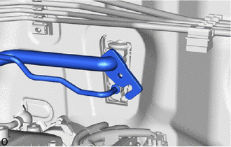
Connect the air conditioning tube assembly.
- NOTICE:
- ·
Do not apply excessive force to the air conditioning tube assembly.
·Make sure not to cut the O-ring while installing it. (Cut O-rings cannot be installed).
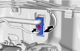
|
|
Install in this Direction |
Rotate the 1-point tightening plate as shown in the illustration.
Insert the tube joint into the fitting hole securely and tighten the bolt.
- Torque:
- 5.4 N*m (55 kgf*cm, 48 in.*lbf)
88716A
50.CONNECT COOLER REFRIGERANT LIQUID PIPE A (w/o Sub-cool Accelerator)
Remove the vinyl tape wrapped around the connection of the cooler refrigerant liquid pipe A.
Sufficiently apply compressor oil to a new O-ring and the fitting surface of the cooler refrigerant liquid pipe A.
- Compressor oil:
ND-OIL 8 or equivalent
Install the O-ring to the cooler refrigerant liquid pipe A.
- NOTICE:
-
Keep the O-rings and O-ring fitting surfaces free of foreign matter.
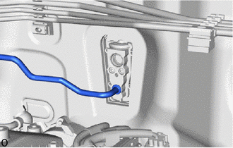
Connect the cooler refrigerant liquid pipe A.
- NOTICE:
- ·
Do not apply excessive force to the cooler refrigerant liquid pipe A.
·Make sure not to cut the O-ring while installing it. (Cut O-rings cannot be installed).
88717A
51.CONNECT COOLER REFRIGERANT SUCTION PIPE A (w/o Sub-cool Accelerator)
Remove the vinyl tape wrapped around the connection of the cooler refrigerant suction pipe A.
Sufficiently apply compressor oil to a new O-ring and the fitting surface of the cooler refrigerant suction pipe A.
- Compressor oil:
ND-OIL 8 or equivalent
Install the O-ring to the cooler refrigerant suction pipe A.
- NOTICE:
-
Keep the O-rings and O-ring fitting surfaces free of foreign matter.
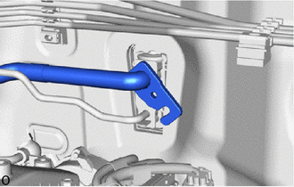
Connect the cooler refrigerant suction pipe A.
- NOTICE:
- ·
Do not apply excessive force to the cooler refrigerant suction pipe A.
·Make sure not to cut the O-ring while installing it. (Cut O-rings cannot be installed).
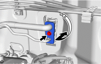
|
|
Install in this Direction |
Rotate the 1-point tightening plate as shown in the illustration.
Insert the pipe joint into the fitting hole securely and tighten the bolt.
- Torque:
- 5.4 N*m (55 kgf*cm, 48 in.*lbf)
55701J
52.INSTALL OUTER COWL TOP PANEL SUB-ASSEMBLY
55738D
53.INSTALL NO. 2 HEATER AIR DUCT SPLASH SHIELD SEAL
47220D
54.CONNECT BRAKE MASTER CYLINDER RESERVOIR ASSEMBLY
55.INSTALL WINDSHIELD WIPER MOTOR AND LINK ASSEMBLY
56.CONNECT CABLE TO NEGATIVE BATTERY TERMINAL
for 7GR-FKS:
for 1GD-FTV:
57. INITIALIZATION AFTER RECONNECTING BATTERY TERMINAL
Click hereGeneral>SETUP>WHEN DISCONNECTING OR RECONNECTING BATTERY TERMINAL>WORK PROCEDURE
- HINT:
-
When disconnecting and reconnecting the battery, there is an automatic learning function that completes learning when the respective system is used.
-
Click hereGeneral>SETUP>WHEN DISCONNECTING OR RECONNECTING BATTERY TERMINAL>AUTOMATIC LEARNING CHART
58.INSPECT WASHER NOZZLE
59. CHARGE AIR CONDITIONING SYSTEM WITH REFRIGERANT
60.ADD ENGINE COOLANT
for 7GR-FKS:
for 1GD-FTV:
61.PERFORM DIAGNOSTIC SYSTEM CHECK
62.CHECK SRS WARNING LIGHT