5L-E ENGINE MECHANICAL ENGINE UNIT INSTALLATION
PROCEDURE

 15609
1.INSTALL OIL FILTER BRACKET SUB-ASSEMBLY
15601
2.INSTALL OIL FILTER SUB-ASSEMBLY
83530
3.INSTALL ENGINE OIL PRESSURE SWITCH ASSEMBLY
17141
4.INSTALL EXHAUST MANIFOLD
17167
5.INSTALL NO. 1 EXHAUST MANIFOLD HEAT INSULATOR
29300B
6.INSTALL VACUUM PUMP OIL OUTLET HOSE
Install the vacuum pump oil outlet hose to the oil pan sub-assembly and slide the clip to secure the hose.
7.INSTALL UNION
Clean the threads of the union and hole.
Apply adhesive to 2 or 3 threads at the end of union.
- Adhesive:
Toyota Genuine Adhesive 1344, Three Bond 1344 or equivalent
Install the union to the cylinder block sub-assembly.
- Torque:
- 28 N*m (286 kgf*cm, 21 ft.*lbf)
29300A
8.INSTALL VACUUM PUMP OIL INLET HOSE
44443
9.INSTALL PUMP BRACKET
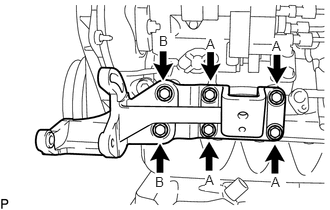
Install the pump bracket with the 6 bolts.
- Torque:
- for bolt A : 57 N*m (581 kgf*cm, 42 ft.*lbf)
- for bolt B : 78 N*m (795 kgf*cm, 58 ft.*lbf)
- Bolt Length:
Item Length Thread Diameter Bolt A 26 mm (1.02 in.) 18 mm (0.709 in.) Bolt B 29 mm (1.14 in.) 19 mm (0.748 in.)
12311
10.INSTALL NO. 1 FRONT ENGINE MOUNTING BRACKET RH
Install the No. 1 front engine mounting bracket RH with the 4 bolts.
- Torque:
- 49 N*m (500 kgf*cm, 36 ft.*lbf)
16291
11.INSTALL WATER HOSE JOINT
Clean the threads of the water hose joint and hole.
Apply adhesive to 2 or 3 threads at the end of the water hose joint.
- Adhesive:
Toyota Genuine Adhesive 1324, Three Bond 1324 or equivalent
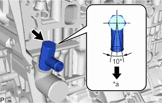
| *a | LH Side |
Install the water hose joint.
- Torque:
- 39 N*m (398 kgf*cm, 29 ft.*lbf)
- NOTICE:
-
Install the water hose joint within 3 minutes after applying adhesive.
Rotate the water hose joint clockwise to the position shown in the illustration.
- NOTICE:
- ·
Do not rotate the water hose joint by more than 1 revolution (360°) after tightening the water hose joint to the specified torque.
·Do not loosen the water hose joint after setting it correctly.
16333
12.INSTALL WATER OUTLET HOUSING
Install a new gasket to the cylinder head sub-assembly.
Install the water outlet hosing with the 3 bolts.
- Torque:
- 19 N*m (194 kgf*cm, 14 ft.*lbf)
88420
13.INSTALL IDLE PULLEY ASSEMBLY WITH BRACKET (w/ Air Conditioning System)
Temporarily install the idle pulley assembly with bracket with the 3 bolts.
Tighten the 3 bolts.
- Torque:
- 46.6 N*m (475 kgf*cm, 34 ft.*lbf)
17111
14.INSTALL INTAKE MANIFOLD
11452
15.INSTALL ENGINE OIL LEVEL DIPSTICK GUIDE
11401G
16.INSTALL CRANKSHAFT POSITION SENSOR
89422C
17.INSTALL ENGINE COOLANT TEMPERATURE SENSOR
22100
18.INSTALL INJECTION PUMP ASSEMBLY
13613P
19.INSTALL INJECTION PUMP DRIVE PULLEY
19850
20.INSTALL GLOW PLUG ASSEMBLY
23600
21.INSTALL NOZZLE HOLDER AND NOZZLE SET
23760
22.INSTALL NOZZLE LEAKAGE PIPE ASSEMBLY
19871
23.INSTALL NO. 1 GLOW PLUG CONNECTOR
23701
24.INSTALL INJECTION PIPE SUB-ASSEMBLY
26100
25.INSTALL VENTURI ASSEMBLY
17114A
26.INSTALL INTAKE FLANGE
13521P
27.INSTALL CRANKSHAFT TIMING PULLEY
13566A
28.INSTALL TIMING BELT GUIDE
29.SET NO. 1 CYLINDER TO TDC/COMPRESSION
13568
30.INSTALL TIMING BELT
11302
31.INSTALL TIMING BELT COVER
13471
32.INSTALL CRANKSHAFT PULLEY
88431
33.INSTALL NO. 1 COMPRESSOR MOUNTING BRACKET (w/ Air Conditioning System)
Install the No. 1 compressor mounting bracket with the 4 bolts.
- Torque:
- 85.9 N*m (876 kgf*cm, 63 ft.*lbf)