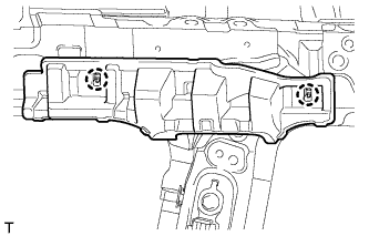
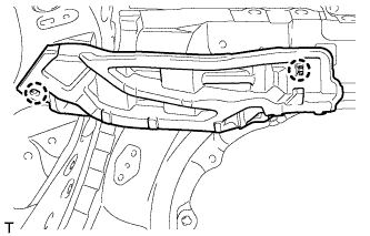
After turning the ignition switch off, waiting time may be required before disconnecting the cable from the battery terminal. Therefore, make sure to read the disconnecting the cable from the battery terminal notice before proceeding with work (Click here).
2.
DISCONNECT CABLE FROM NEGATIVE BATTERY TERMINAL
NOTICE:
When disconnecting the cable, some systems need to be initialized after the cable is reconnected (Click here).
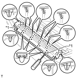
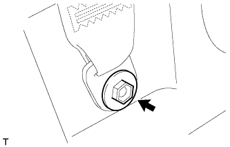
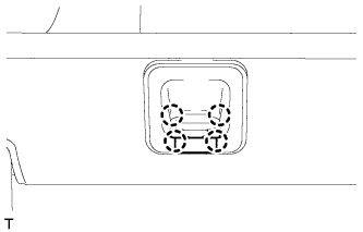
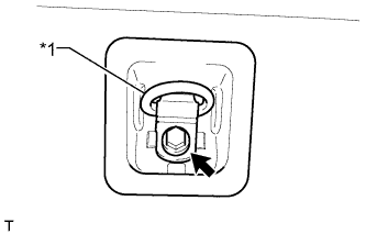
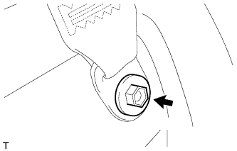
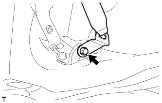
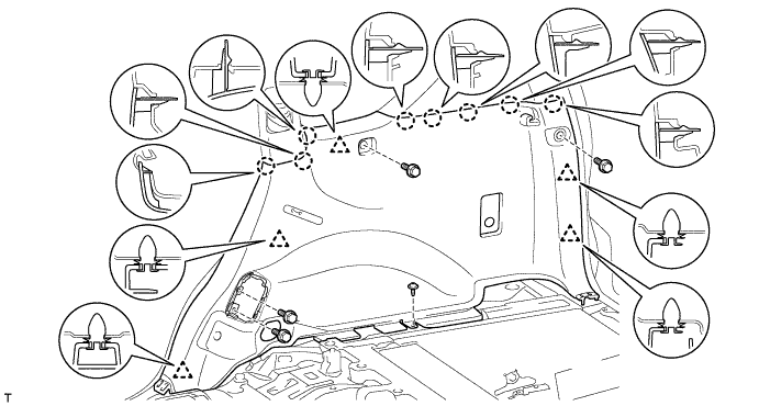
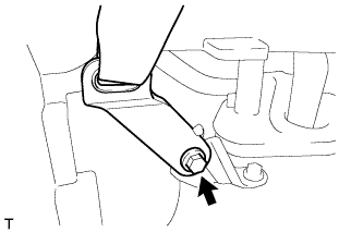
Remove the bolt and disconnect the rear No. 1 seat outer belt floor anchor.
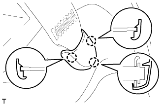
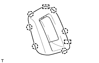
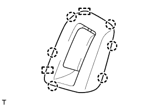
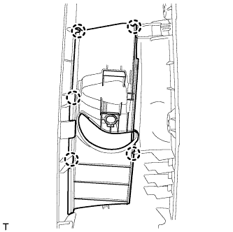
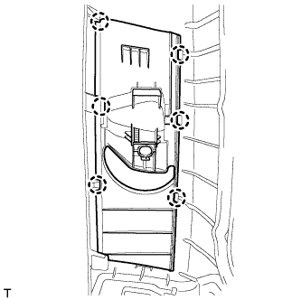
Detach the 6 claws and 2 guides and disconnect the rear seatback lock control lever base.
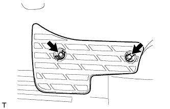
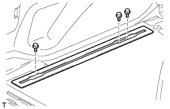
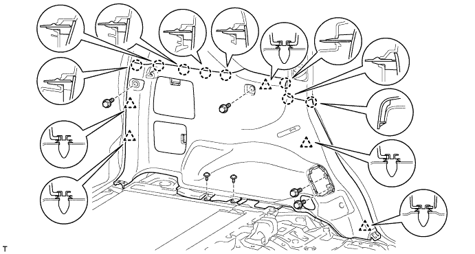
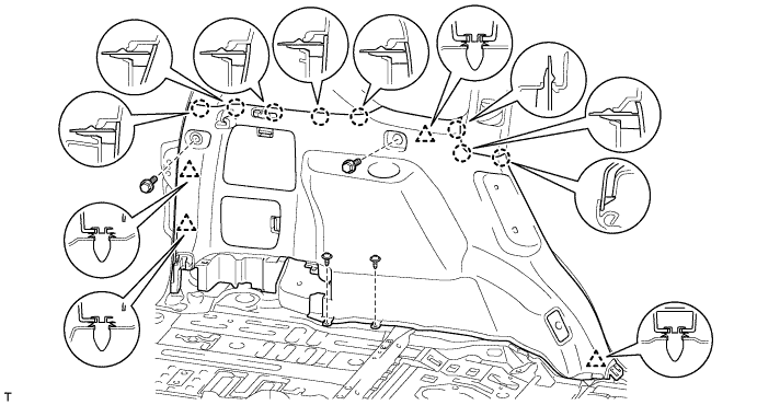
Remove the 4 bolts and 2 screws.
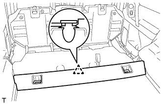
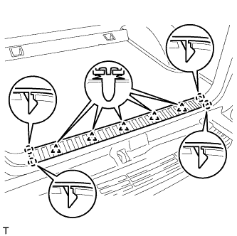
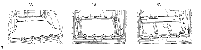
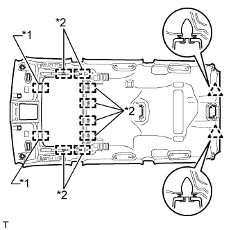
Detach the 5 clips and 8 claws.
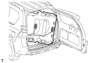
Pass the rear seatback lock control lever base through the deck trim side panel and remove the deck trim side panel.
w/ Rear No. 2 Seat:
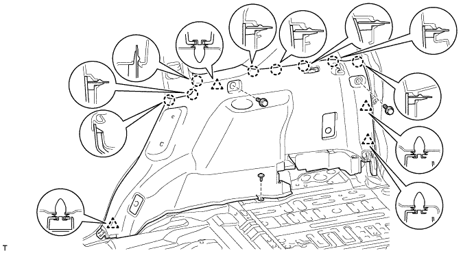
Remove the bolt and disconnect the rear No. 1 seat outer belt floor anchor.
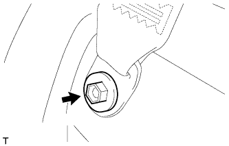
Remove the bolt and disconnect the rear No. 2 seat outer belt floor anchor.
Remove the 2 bolts and 2 screws.
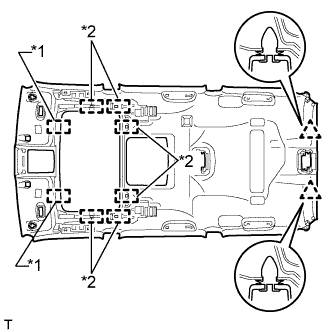
Detach the 4 clips and 8 claws and remove the deck trim side panel.
46.
REMOVE DECK TRIM SIDE PANEL ASSEMBLY RH
w/o Rear No. 2 Seat:
Remove the bolt and disconnect the rear No. 1 seat outer belt floor anchor.
Detach the 6 claws and 2 guides and disconnect the rear seatback lock control lever base.
Remove the 4 bolts and screws.
Detach the 5 clips and 8 claws.
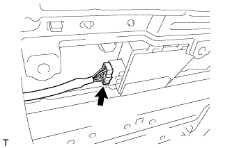
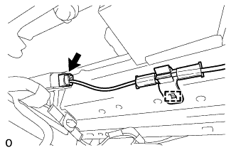
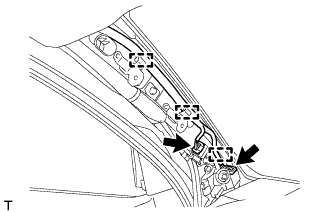
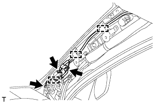
Disconnect each connector.
Pass the rear seatback lock control lever base through the deck trim side panel and remove the deck trim side panel.
w/ Rear No. 2 Seat:
Remove the bolt and disconnect the rear No. 1 seat outer belt floor anchor.
Remove the bolt and disconnect the rear No. 2 seat outer belt floor anchor.
Remove the 2 bolts and screw.
Detach the 4 clips and 8 claws.
Disconnect each connector and remove the deck trim side panel.
47.
REMOVE FRONT QUARTER TRIM PANEL ASSEMBLY LH
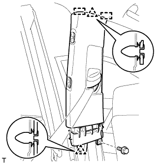
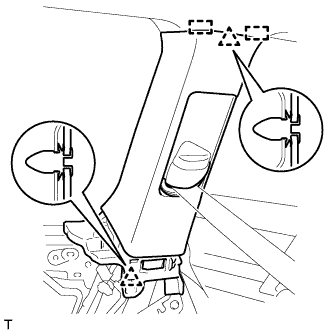
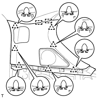
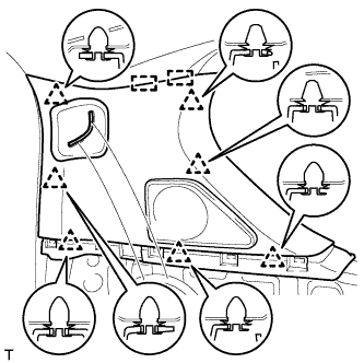
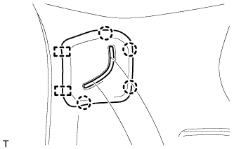
Move the rear shoulder belt anchor adjuster to the lowest position.
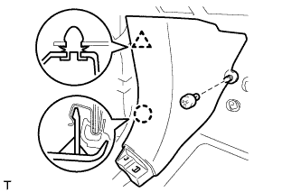
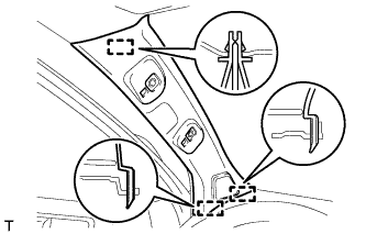
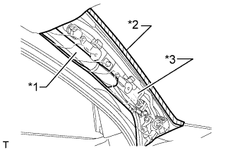
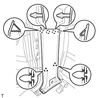
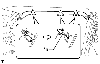
Detach the 2 clips and 2 guides.
Pass the rear No. 1 seat outer belt floor anchor through the front quarter trim panel and remove the front quarter trim panel.
48.
REMOVE FRONT QUARTER TRIM PANEL ASSEMBLY RH
HINT:
Use the same procedure described for the LH side.
49.
REMOVE REAR QUARTER TRIM PANEL ASSEMBLY LH
w/o Rear No. 2 Seat:
Detach the 7 clips and 2 guides and remove the rear quarter trim panel.
w/ Rear No. 2 Seat:
Detach the 7 clips and 2 guides.
Detach the 4 clips and 2 guides, pass the rear No. 2 seat outer belt floor anchor through the rear quarter trim panel and remove the rear quarter trim panel.
50.
REMOVE REAR QUARTER TRIM PANEL ASSEMBLY RH
HINT:
Use the same procedure described for the LH side.
51.
REMOVE ASSIST GRIP SUB-ASSEMBLY
HINT:
Use the same procedure for the other assist grip.
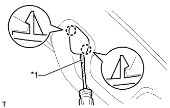
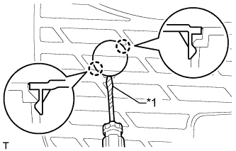
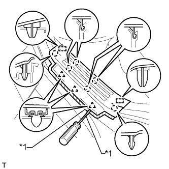
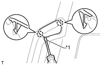
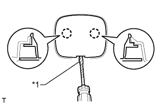
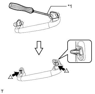
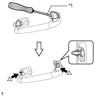
Using a screwdriver, detach the 4 claws and remove the 2 assist grip covers.
HINT:
Tape the screwdriver tip before use.
Text in Illustration
*1
Protective Tape
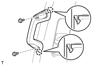
Detach the 2 clips and remove the assist grip.
Remove the 2 clips from the vehicle body.
52.
REMOVE REAR ASSIST GRIP ASSEMBLY LH
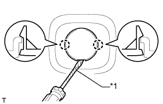
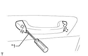
Using a screwdriver, detach the 4 claws and remove the 2 assist grip covers.
HINT:
Tape the screwdriver tip before use.
Text in Illustration
*1
Protective Tape
Detach the 2 clips and remove the assist grip.
Remove the 2 clips from the vehicle body.
53.
REMOVE REAR ASSIST GRIP ASSEMBLY RH
HINT:
Use the same procedure described for the LH side.
54.
REMOVE ASSIST GRIP (w/ Rear No. 2 Seat)
HINT:
Use the same procedure for the other assist grip.
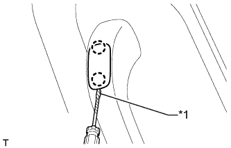
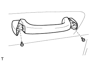
Using a screwdriver, detach the 4 claws and open the 2 covers.
HINT:
Tape the screwdriver tip before use.
Text in Illustration
*1
Protective Tape
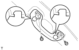
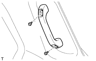
Remove the 2 bolts and assist grip.
55.
REMOVE VISOR BRACKET COVER LH
HINT:
Use the same procedure for the other visor bracket cover.
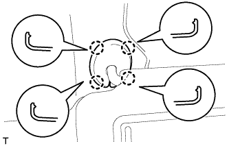
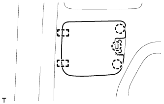
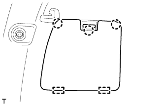
Detach the 4 claws and remove the visor bracket cover.
56.
REMOVE VISOR BRACKET COVER RH
HINT:
Use the same procedure described for the LH side.
57.
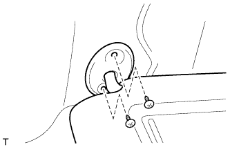
REMOVE VISOR ASSEMBLY LH
Remove the 2 screws and visor.
58.
REMOVE VISOR ASSEMBLY RH
HINT:
Use the same procedure described for the LH side.
59.
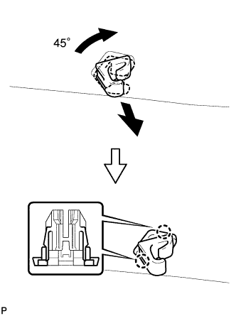
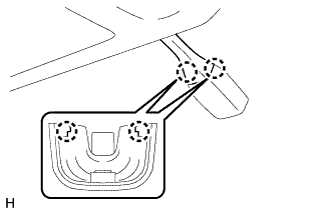
REMOVE VISOR HOLDER
HINT:
Use the same procedure for the other visor holder.
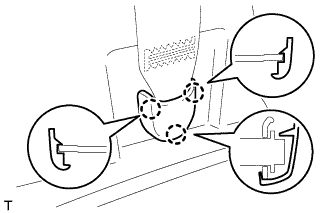
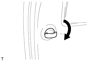
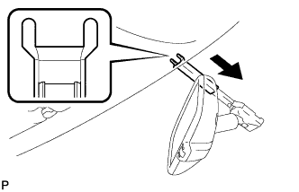
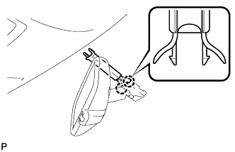
Turn the visor holder approximately 45° and pull it out as shown in the illustration.
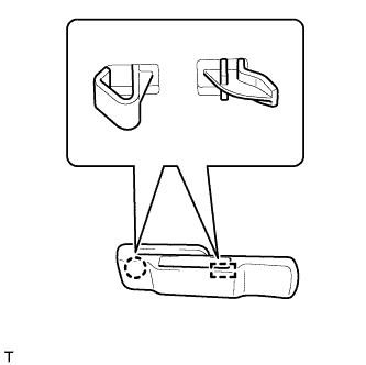
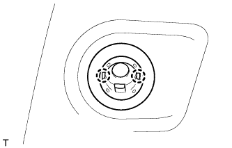
Detach the 2 claws and remove the visor holder.
60.
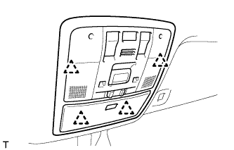
REMOVE MAP LIGHT ASSEMBLY
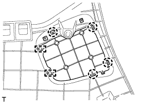
Detach the 4 clips.
Disconnect the connector and remove the map light.
61.
REMOVE RAIN SENSOR COVER (w/ Rain Sensor)
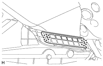
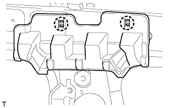
Detach the 2 claws and remove the rain sensor cover.