1KD-FTV ENGINE MECHANICAL CYLINDER HEAD GASKET REMOVAL
CAUTION / NOTICE / HINT
- NOTICE:
- ·
When replacing the injectors (including shuffling the injectors between the cylinders), common rail or cylinder head, it is necessary to replace the injection pipes with new ones.
·When replacing the fuel supply pump, common rail, cylinder block, cylinder head, cylinder head gasket or timing gear case, it is necessary to replace the fuel inlet pipe with a new one.
PROCEDURE

 1.DISCONNECT CABLE FROM NEGATIVE BATTERYTERMINAL
- NOTICE:
- ·
After turning the ignition switch off, waiting time may be required before disconnecting the cable from the battery terminal. Therefore, make sure to read the disconnecting the cable from the battery terminal notice before proceeding with work (See page General>INTRODUCTION>REPAIR INSTRUCTION>PRECAUTION).
·When disconnecting the cable, some systems need to be initialized after the cable is reconnected (See page General>INTRODUCTION>REPAIR INSTRUCTION>INITIALIZATION).
52129B
2.REMOVE FRONT BUMPER LOWER COVER
51405A
3.REMOVE NO. 1 ENGINE UNDER COVER SUB-ASSEMBLY
4.DRAIN ENGINE COOLANT
5.DRAIN ENGINE OIL
17141
6.REMOVE EXHAUST MANIFOLD WITH TURBOCHARGER
Remove the exhaust manifold with turbocharger (See page Engine / Hybrid System>1KD-FTV (INTAKE / EXHAUST)>EXHAUST MANIFOLD W/ TURBOCHARGER>REMOVAL).
17111
7.REMOVE INTAKE MANIFOLD
Remove the intake manifold (See page Engine / Hybrid System>1KD-FTV (INTAKE / EXHAUST)>INTAKE MANIFOLD>REMOVAL).
19850
8.REMOVE GLOW PLUG ASSEMBLY
Remove the glow plugs (See page Engine / Hybrid System>1KD-FTV (STARTING)>GLOW PLUG>REMOVAL).
17136
9.REMOVE NO. 2 INTAKE MANIFOLD INSULATOR
23804C
10.REMOVE FUEL INLET PIPE SUB-ASSEMBLY
23810A
11.REMOVE COMMON RAIL ASSEMBLY
11202D
12.REMOVE NO. 2 CYLINDER HEAD COVER SUB-ASSEMBLY
25708
13.REMOVE NO. 3 VACUUM TRANSMITTING PIPE SUB-ASSEMBLY
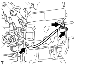
Disconnect the vacuum hose.
Remove the bolt and No. 3 vacuum transmitting pipe.
23681A
14.REMOVE NOZZLE HOLDER SEAL
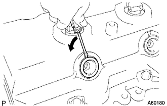
Using a small screwdriver, remove the 4 holder seals by prying between each holder seal and the cutout part of the cylinder head cover.
11201
15.REMOVE CYLINDER HEAD COVER SUB-ASSEMBLY
- NOTICE:
-
If the cylinder head cover is removed, replace the 4 No. 3 cylinder head cover gaskets with new ones.
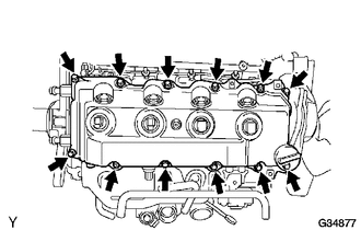
Remove the 10 bolts, 2 nuts, cylinder head cover and gasket.
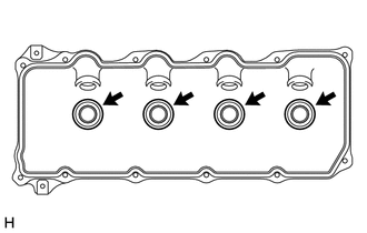
Remove the 4 No. 3 cylinder head cover gaskets from the cylinder head cover.
23670
16.REMOVE INJECTOR ASSEMBLY
13568
17.REMOVE TIMING BELT
Remove the timing belt (See page Engine / Hybrid System>1KD-FTV (ENGINE MECHANICAL)>TIMING BELT>REMOVAL).
13505
18.REMOVE NO. 1 TIMING BELT IDLER SUB-ASSEMBLY
13523P
19.REMOVE CAMSHAFT TIMING PULLEY
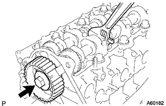
Remove the bolt of the camshaft timing pulley while holding the camshaft with a wrench.
- NOTICE:
-
Make sure the timing belt is not installed when removing the bolt of camshaft timing pulley.
Remove the camshaft timing pulley.
11322B
20.REMOVE NO. 2 TIMING BELT COVER
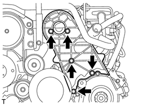
Remove the 4 bolts, nuts and No. 2 timing belt cover.
12581C
21.REMOVE CYLINDER BLOCK INSULATOR
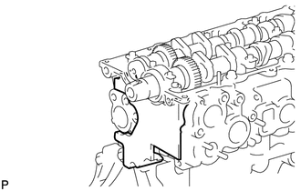
Remove the cylinder block insulator from the cylinder head.
13511
22.REMOVE CAMSHAFT
11101
23.REMOVE CYLINDER HEAD SUB-ASSEMBLY
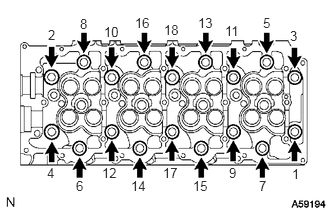
Uniformly loosen the 18 cylinder head bolts in several passes in the sequence shown in the illustration. Then remove the 18 cylinder head bolts and 18 washers.
- NOTICE:
-
Head warpage or cracking could result from removing bolts in the incorrect order.
Remove the cylinder head from the dowels on the cylinder block and place the cylinder head on wooden blocks on a workbench.
- HINT:
-
If the cylinder head is difficult to remove, use a screwdriver to pry between the cylinder head and block.
- NOTICE:
-
Be careful not to damage the contact surfaces of the cylinder head and cylinder block.
11115
24.REMOVE CYLINDER HEAD GASKET