1GD-FTV ENGINE MECHANICAL CAMSHAFT INSTALLATION
CAUTION / NOTICE / HINT
- NOTICE:
- ·
When replacing the parts in the following chart (A), replace the No. 1 injection pipe sub-assembly, No. 2 injection pipe sub-assembly and/or fuel inlet pipe sub-assembly with new ones.
Replaced Parts (A) Pipes Requiring New Replacement Injector assembly (including shuffling the injector assemblies between the cylinders) ·No. 1 injection pipe sub-assembly
·No. 1 injection pipe sub-assembly
Supply pump assembly Fuel inlet pipe sub-assembly ·Common rail assembly
·Cylinder block sub-assembly
·Cylinder head sub-assembly
·Cylinder head gasket
·Timing chain case assembly
·No. 1 injection pipe sub-assembly
·No. 2 injection pipe sub-assembly
·Fuel inlet pipe sub-assembly
·After removing the No. 1 injection pipe sub-assembly, No. 2 injection pipe sub-assembly and/or fuel inlet pipe sub-assembly, clean them with a brush and compressed air.
·The injector assembly is a precision instrument. Do not use the injector assembly if it is struck or dropped.
·The supply pump assembly is a precision instrument. Do not use the supply pump assembly if it is struck or dropped.
·Hold the supply pump assembly itself during removal and installation. Do not hold the pre-stroke control valve or fuel pipe, etc.
·Make sure foreign matter does not enter the fuel path.
PROCEDURE

 1.INSTALL CAMSHAFT
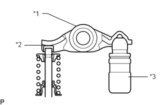
Check that the valve rocker arm sub-assembly is firmly set to the valve lash adjuster assembly.
| *1 | Valve Rocker Arm Sub-assembly |
| *2 | Valve Stem Cap |
| *3 | Valve Lash Adjuster Assembly |
Apply a light coat of engine oil to the camshaft journals of the cylinder head sub-assembly and the thrust portion of the camshaft.
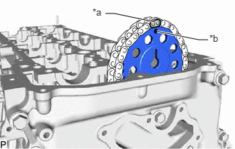
Align the paint mark of the No. 2 chain sub-assembly and timing mark of the camshaft timing sprocket, and install the camshaft timing sprocket to the No. 2 chain sub-assembly.
- HINT:
-
Make sure the timing mark of the camshaft timing sprocket face the front side.
| *a | Paint Mark |
| *b | Timing Mark |
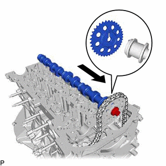
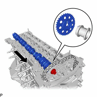
Align the knock pin of the No. 1 camshaft to the groove of the sprocket and install the No. 1 camshaft to the camshaft timing sprocket, and set the bolt.
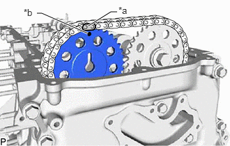
Align the paint mark of the No. 2 chain sub-assembly and timing mark of the camshaft timing sprocket, and install the camshaft timing sprocket to the No. 2 chain sub-assembly.
- HINT:
-
Make sure the timing mark of the camshaft timing sprocket face the front side.
| *a | Paint Mark |
| *b | Timing Mark |
Align the knock pin of the No. 2 camshaft to the groove of the sprocket and install the No. 2 camshaft to the camshaft timing sprocket, and set the bolt.
- HINT:
-
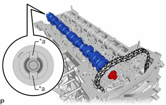 0.802,0.865 0.729,0.865 0.729,0.865 0.677,1.156 false 0.802,1.865 0.729,1.865 0.729,1.865 0.677,1.573 false 0.813,0.771 1.271,1.01 0.458,0.24 10 false *a 0.802,1.76 1.26,2 0.458,0.24 10 false *a
-
Glove is at the rear end of the No. 2 camshaft.
Text in Illustration *a Glove
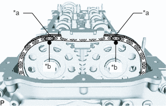
Check the timing mark of the camshaft timing sprocket and the paint mark of the No. 2 chain sub-assembly.
| *a | Paint Mark |
| *b | Timing Mark |
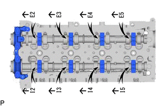
Set the No. 1 camshaft bearing cap and 8 No. 2 camshaft bearing caps to the cylinder head sub-assembly as shown in the illustration.
Temporarily install the 20 bolts.
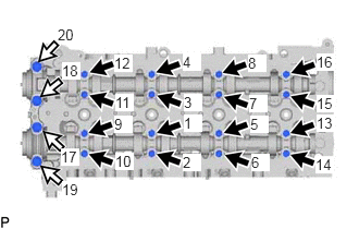
Uniformly tighten the 20 bolts in several steps in the order shown in the illustration.
- Torque:
- for bolt A : 10 N*m (102 kgf*cm, 7 ft.*lbf)
- for bolt B : 21 N*m (214 kgf*cm, 15 ft.*lbf)

|
Bolt A |

|
Bolt B |
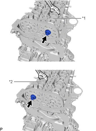
Hold the hexagonal portion of the No. 1 camshaft and No. 2 camshaft with a wrench, and tighten the 2 bolts.
- Torque:
- 81 N*m (826 kgf*cm, 60 ft.*lbf)
- NOTICE:
-
Be careful not to damage the cylinder head sub-assembly with the wrench.
| *1 | No. 1 Camshaft |
| *2 | No. 2 Camshaft |
Remove the pin from the No. 2 chain tensioner assembly.
Install a new gasket and the oil pump relief valve plug to the timing chain cover.
- Torque:
- 46 N*m (469 kgf*cm, 34 ft.*lbf)
Clean and degrease the contact surfaces of the cylinder head sub-assembly and No. 3 camshaft bearing cap.
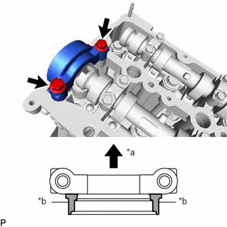
Apply seal packing to the specified areas as shown in the illustration.
- Seal packing:
Toyota Genuine Seal Packing Black, Three Bond 1207B or equivalent
- Standard seal diameter:
3.0 mm (0.118 in.)
- NOTICE:
- ·
Do not allow seal packing to contact the oil passage of the No. 3 camshaft bearing cap.
·After applying seal packing, install the No. 3 camshaft bearing cap within 3 minutes and tighten the bolts within 10 minutes.
·Do not start the engine for at least 2 hours after installation.
| *a | Engine Front |
| *b | Seal Packing |
Install the No. 3 camshaft bearing cap with the 2 bolts.
- Torque:
- 21 N*m (214 kgf*cm, 15 ft.*lbf)
Wipe off excess seal packing from between No. 3 camshaft bearing cap and cylinder head sub-assembly.
13566B
2.INSTALL TIMING CHAIN GUIDE
Install the timing chain guide to the cylinder head sub-assembly with the bolt.
- Torque:
- 10 N*m (102 kgf*cm, 7 ft.*lbf)
11201
3.INSTALL CYLINDER HEAD COVER SUB-ASSEMBLY
23682
4.INSTALL NOZZLE HOLDER GASKET
23670
5.TEMPORARILY INSTALL INJECTOR ASSEMBLY
6.TEMPORARILY INSTALL NO. 1 INJECTION PIPE SUB-ASSEMBLY AND NO. 2 INJECTION PIPE SUB-ASSEMBLY
23670
7.TIGHTEN INJECTOR ASSEMBLY
8.TIGHTEN NO. 1 INJECTION PIPE SUB-ASSEMBLY AND NO. 2 INJECTION PIPE SUB-ASSEMBLY
23760
9.INSTALL NOZZLE LEAKAGE PIPE ASSEMBLY
10.INSTALL HARNESS BRACKET
11.INSTALL WIRING HARNESS CLAMP BRACKET
12.INSTALL NO. 1 EGR COOLER WITH ELECTRIC EGR CONTROL VALVE ASSEMBLY
25804
13.INSTALL VACUUM CONTROL VALVE SET
25601
14.INSTALL NO. 1 EGR PIPE SUB-ASSEMBLY
16209
15.CONNECT NO. 4 WATER BY-PASS PIPE SUB-ASSEMBLY
16206B
16.INSTALL NO. 3 WATER BY-PASS PIPE SUB-ASSEMBLY
25612
17.INSTALL NO. 2 EGR PIPE
25625
18.INSTALL EGR VALVE BRACKET
89421C
19.INSTALL TURBO PRESSURE SENSOR
23265C
20.INSTALL GAS FILTER
26100G
21.INSTALL DIESEL THROTTLE BODY ASSEMBLY
77246C
22.INSTALL FUEL MAIN TUBE SUPPORT (w/ Urea SCR System)
17360A
23.INSTALL AIR TUBE ASSEMBLY (w/o Urea SCR System)
89463C
24.CONNECT NO. 1 NITROGEN OXIDES SENSOR (w/ Urea SCR System)
12631A
25.INSTALL ENGINE COVER BRACKET
17578B
26.INSTALL PIPE CLAMP
25734
27.TEMPORARILY INSTALL NO. 2 VACUUM PIPE
25733A
28.TEMPORARILY INSTALL NO. 1 VACUUM PIPE
25734
29.TIGHTEN NO. 2 VACUUM PIPE
25733A
30.TIGHTEN NO. 1 VACUUM PIPE
89425
31.INSTALL EXHAUST GAS TEMPERATURE SENSOR
89481B
32.INSTALL DIFFERENTIAL PRESSURE SENSOR
17168
33.INSTALL NO. 2 EXHAUST MANIFOLD HEAT INSULATOR
23295D
34.INSTALL NO. 1 INJECTOR HOLDER
16282
35.CONNECT NO. 5 WATER BY-PASS HOSE
16281
36.CONNECT NO. 4 WATER BY-PASS HOSE
12203
37.INSTALL PCV PIPE SUB-ASSEMBLY (for Cold Area Specification Vehicles)
12261
38.INSTALL PCV HOSE (except Cold Area Specification Vehicles)
23811H
39.INSTALL NO. 1 FUEL PIPE
12632
40.INSTALL NO. 2 ENGINE COVER BRACKET (w/o Urea SCR System)
12633
41.INSTALL NO. 3 ENGINE COVER BRACKET (w/o Urea SCR System)
16278
42.INSTALL NO. 2 WATER BY-PASS PIPE
11382C
43.INSTALL CAMSHAFT OIL SEAL RETAINER
29300
44.INSTALL VACUUM PUMP ASSEMBLY
45.INSTALL ENGINE ASSEMBLY