1GD-FTV EMISSION CONTROL MONOLITHIC CONVERTER INSTALLATION
PROCEDURE

 89463C
1.INSTALL NO. 1 NITROGEN OXIDES SENSOR (w/ Urea SCR System)
25051
2.INSTALL EXHAUST MANIFOLD CONVERTER SUB-ASSEMBLY
Set a new gasket and the exhaust manifold converter sub-assembly to the turbocharger sub-assembly.
Temporarily install the exhaust pipe support stay to the cylinder block sub-assembly and exhaust manifold converter sub-assembly with the 3 bolts.
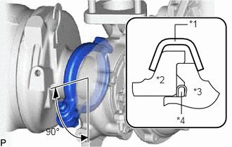
Install a new exhaust pipe clamp to the exhaust manifold converter sub-assembly with a new nut.
- Torque:
- 18 N*m (184 kgf*cm, 13 ft.*lbf)
| *1 | Exhaust Pipe Clamp |
| *2 | Exhaust Manifold Converter |
| *3 | Turbocharger Sub-assembly |
| *4 | Gasket |
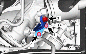
Tighten the 3 bolts and install the exhaust pipe support stay to the cylinder block sub-assembly and exhaust manifold converter sub-assembly in the order shown in the illustration.
- Torque:
- 38 N*m (387 kgf*cm, 28 ft.*lbf)
w/ Rear Air Conditioning System:
Connect the heater water hose to the heater water pipe, and slide the 4 clamps to secure the hose.
w/ Rear Air Conditioning System:
Install the heater hose with the bolt.
- Torque:
- 5.4 N*m (55 kgf*cm, 48 in.*lbf)
Install the No. 3 skid control sensor clamp to the body with the bolt.
- Torque:
- 5.0 N*m (51 kgf*cm, 44 in.*lbf)
17118
3.INSTALL NO. 2 EXHAUST PIPE SUPPORT STAY
Temporarily install the No. 2 exhaust pipe support stay to the cylinder block sub-assembly and exhaust manifold converter sub-assembly with the bolt and 2 new nuts.
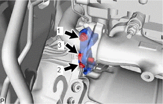
Tighten the bolt and 2 nuts and install the No. 2 exhaust pipe support stay to the cylinder block sub-assembly and exhaust manifold converter sub-assembly in the order shown in the illustration.
- Torque:
- 38 N*m (387 kgf*cm, 28 ft.*lbf)
89463C
4.CONNECT NO. 1 NITROGEN OXIDES SENSOR (w/ Urea SCR System)
Install the exhaust sensor clamp bracket to the cylinder head sub-assembly with the bolt.
- Torque:
- 13 N*m (133 kgf*cm, 10 ft.*lbf)
Attach the 4 clamps and connect the No. 1 nitrogen oxides sensor.
Install the 2 bolts.
- Torque:
- 13 N*m (133 kgf*cm, 10 ft.*lbf)
Connect the connector to the No. 1 nitrogen oxides sensor.
17271
5.INSTALL NO. 1 TURBO INSULATOR
Install the No. 1 turbo insulator to the exhaust manifold and turbocharger sub-assembly with the 3 bolts.
- Torque:
- 12 N*m (122 kgf*cm, 9 ft.*lbf)
17167
6.INSTALL NO. 1 EXHAUST MANIFOLD HEAT INSULATOR
Install the No. 1 exhaust manifold heat insulator to the exhaust manifold with the 3 bolts.
- Torque:
- 12 N*m (122 kgf*cm, 9 ft.*lbf)
89467B
7.INSTALL AIR FUEL RATIO SENSOR (w/o Urea SCR System)
45220
8.CONNECT STEERING INTERMEDIATE SHAFT ASSEMBLY (for RHD)
12631A
9.INSTALL ENGINE COVER BRACKET
Install the engine cover bracket to the cylinder head sub-assembly with the 2 bolts.
- Torque:
- 21 N*m (214 kgf*cm, 15 ft.*lbf)
w/ Urea SCR System:
Attach the clamp and connect the engine wire to the engine cover bracket with the bolt.
- Torque:
- 8.0 N*m (82 kgf*cm, 71 in.*lbf)
w/o Urea SCR System:
Attach the 2 clamps and connect the engine wire to the cylinder head sub-assembly.
17578B
10.INSTALL PIPE CLAMP
Install the pipe clamp to the engine cover bracket with the 3 bolts.
- Torque:
- 10 N*m (102 kgf*cm, 7 ft.*lbf)
25734
11.TEMPORARILY INSTALL NO. 2 VACUUM PIPE
Install a new clamp to the pipe clamp.
Temporarily install the No. 2 vacuum pipe to the exhaust manifold converter sub-assembly.
25733A
12.TEMPORARILY INSTALL NO. 1 VACUUM PIPE
Temporarily install the No. 1 vacuum pipe to the exhaust manifold converter sub-assembly.
Install a new clamp to the No. 1 vacuum pipe and No. 2 vacuum pipe with the nut.
- Torque:
- 6.0 N*m (61 kgf*cm, 53 in.*lbf)
25734
13.TIGHTEN NO. 2 VACUUM PIPE
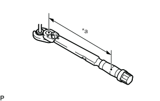
Using a 17 mm union nut wrench, tighten the No. 2 vacuum pipe.
- Torque:
Specified tightening torque
48 N*m {489 kgf*cm, 35 ft.*lbf}
| *a | Torque Wrench Fulcrum Length |
- HINT:
- ·
Calculate the torque wrench reading when changing the fulcrum length of the torque wrench (See page General>INTRODUCTION>REPAIR INSTRUCTION>PRECAUTION).
·When using a union nut wrench (fulcrum length of 30 mm (1.18 in.)) + torque wrench (fulcrum length of 255 mm (10.0 in.)): 43 N*m (437 kgf*cm, 32 ft.*lbf)
25733A
14.TIGHTEN NO. 1 VACUUM PIPE
Using a 17 mm union nut wrench, tighten the No. 1 vacuum pipe.
- Torque:
Specified tightening torque
48 N*m {489 kgf*cm, 35 ft.*lbf}
| *a | Torque Wrench Fulcrum Length |
- HINT:
- ·
Calculate the torque wrench reading when changing the fulcrum length of the torque wrench (See page General>INTRODUCTION>REPAIR INSTRUCTION>PRECAUTION).
·When using a union nut wrench (fulcrum length of 30 mm (1.18 in.)) + torque wrench (fulcrum length of 255 mm (10.0 in.)): 43 N*m (437 kgf*cm, 32 ft.*lbf)
89425
15.INSTALL EXHAUST GAS TEMPERATURE SENSOR
12633
16.INSTALL NO. 3 ENGINE COVER BRACKET (w/o Urea SCR System)
89481B
17.INSTALL DIFFERENTIAL PRESSURE SENSOR
18.INSTALL AIR CLEANER CASE SUB-ASSEMBLY
17801
19.INSTALL AIR CLEANER FILTER ELEMENT SUB-ASSEMBLY
17705
20.INSTALL AIR CLEANER CAP SUB-ASSEMBLY WITH AIR CLEANER HOSE
53736B
21.INSTALL NO. 1 FRONT FENDER APRON TO FRAME SEAL RH
17168
22.INSTALL NO. 2 EXHAUST MANIFOLD HEAT INSULATOR
17410
23.INSTALL FRONT EXHAUST PIPE ASSEMBLY
24.BLEED AIR FROM FUEL SYSTEM
25.ADD ENGINE COOLANT (w/ Urea SCR System)
26.ADD ENGINE COOLANT
27.INSPECT FOR COOLANT LEAK (w/ Urea SCR System)
28.INSPECT FOR COOLANT LEAK