5L-E ENGINE MECHANICAL CAMSHAFT INSTALLATION
PROCEDURE

 13511
1.INSTALL CAMSHAFT
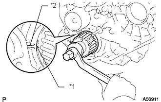
Check that the timing mark of the crankshaft timing pulley is in the position shown in the illustration.
| *1 | Timing Mark |
| *2 | Protrusion |
Install the camshaft.
Place the camshaft on the cylinder head with the key groove facing upward.
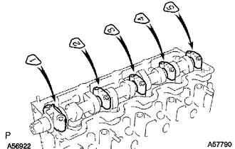
Install the 5 bearing caps in their proper locations.
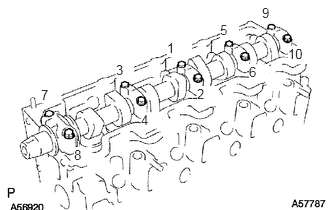
Apply a light coat of engine oil to the threads and under the heads of the bearing cap bolts.
Install and uniformly tighten the 10 bearing cap bolts in several steps in the sequence shown in the illustration.
- Torque:
- 25 N*m (255 kgf*cm, 18 ft.*lbf)
11305A
2.INSTALL CAMSHAFT OIL SEAL
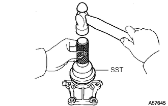
Using SST and a hammer, tap in a new oil seal until its surface is flush with the oil seal retainer edge.
- SST
- 09960-10010 (09962-01000, 09963-01000)
Apply MP grease to the lip of the oil seal.
11385
3.INSTALL CAMSHAFT OIL SEAL RETAINER
Install a new gasket and the retainer with the 4 bolts.
- Torque:
- 18 N*m (184 kgf*cm, 13 ft.*lbf)
11322B
4.INSTALL NO. 2 TIMING BELT COVER
Install the timing belt cover with the 4 bolts.
- Torque:
- 18 N*m (184 kgf*cm, 13 ft.*lbf)
13523P
5.INSTALL CAMSHAFT TIMING PULLEY
Install the woodruff key to the key groove of the camshaft.
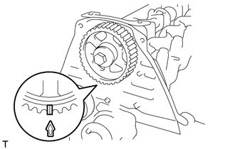
Align the timing mark on the camshaft timing pulley with the timing mark on the No. 2 timing belt cover and temporarily install the pulley with the bolt.
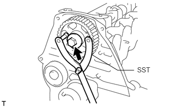
Using SST, tighten the bolt.
- SST
- 09960-10010 (09962-01000, 09963-01000)
- Torque:
- 98 N*m (999 kgf*cm, 72 ft.*lbf)
6.SET NO. 1 CYLINDER TO TDC/COMPRESSION
13568
7.INSTALL TIMING BELT
8.CHECK NO. 1 CYLINDER TO TDC/COMPRESSION
13566A
9.INSTALL TIMING BELT GUIDE
10.INSPECT VALVE CLEARANCE
11.ADJUST VALVE CLEARANCE
11201
12.INSTALL CYLINDER HEAD COVER SUB-ASSEMBLY
17130
13.INSTALL INTAKE PIPE
11302
14.INSTALL TIMING BELT COVER
88545
15.INSTALL IDLE PULLEY ASSEMBLY
13471
16.INSTALL CRANKSHAFT PULLEY
44319
17.INSTALL VANE PUMP DRIVE PULLEY
16711
18.INSTALL FAN SHROUD
16470
19.INSTALL RADIATOR RESERVE TANK ASSEMBLY
16571C
20.INSTALL NO. 1 RADIATOR HOSE
82715
21.INSTALL WIRING HARNESS CLAMP BRACKET (for LHD)
22.CONNECT WIRE HARNESS
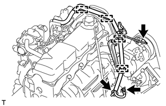
Attach the 4 wire harness clamps.
Install the generator wire with the nut.
- Torque:
- 9.8 N*m (100 kgf*cm, 87 in.*lbf)
Install the terminal cap.
Connect the generator connector and cooler compressor connector.
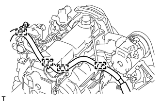
for LHD:
Attach the 4 wire harness clamps.
17700
23.INSTALL AIR CLEANER CASE ASSEMBLY
17801
24.INSTALL AIR CLEANER FILTER ELEMENT SUB-ASSEMBLY
25.INSTALL RESONATOR WITH AIR CLEANER CAP SUB-ASSEMBLY
53736
26.INSTALL FRONT FENDER APRON SEAL RH
27.ADD ENGINE COOLANT
28.CONNECT CABLE TO NEGATIVE BATTERY TERMINAL
29. INITIALIZATION AFTER RECONNECTING BATTERY TERMINAL
Click hereGeneral>SETUP>WHEN DISCONNECTING OR RECONNECTING BATTERY TERMINAL>WORK PROCEDURE
- HINT:
-
When disconnecting and reconnecting the battery, there is an automatic learning function that completes learning when the respective system is used.
-
Click hereGeneral>SETUP>WHEN DISCONNECTING OR RECONNECTING BATTERY TERMINAL>AUTOMATIC LEARNING CHART
30.INSPECT FOR ENGINE COOLANT LEAK
31.INSPECT ENGINE IDLE SPEED
32.INSPECT MAXIMUM ENGINE SPEED
51405A
33.INSTALL NO. 1 ENGINE UNDER COVER SUB-ASSEMBLY
52129B
34.INSTALL FRONT BUMPER COVER LOWER
53292A
35.INSTALL UPPER RADIATOR SUPPORT SEAL