1GR-FE ENGINE MECHANICAL CAMSHAFT INSTALLATION
CAUTION / NOTICE / HINT
- HINT:
-
for Automatic Transmission:
-
Perform "Inspection After Repairs" after replacing the camshaft (intake or exhaust side) or camshaft timing gear assembly (intake or exhaust side) (See page Engine / Hybrid System>1GR-FE (ENGINE CONTROL)>SFI SYSTEM>INITIALIZATION).
PROCEDURE

 13050
1.INSPECT CAMSHAFT TIMING GEAR ASSEMBLY
13070A
2.INSPECT CAMSHAFT TIMING EXHAUST GEAR ASSEMBLY
13050
3.INSTALL CAMSHAFT TIMING GEAR ASSEMBLY
- HINT:
-
for Automatic Transmission:
-
Perform "Inspection After Repairs" after replacing the camshaft timing gear assembly (See page Engine / Hybrid System>1GR-FE (ENGINE CONTROL)>SFI SYSTEM>INITIALIZATION).
Fix the camshaft in place.
- NOTICE:
-
Be careful not to damage the camshaft.
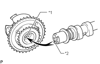
Put the camshaft timing gear assembly and camshaft together by aligning the pin hole and straight pin.
| *1 | Pin Hole |
| *2 | Straight Pin |
Lightly press and turn the camshaft timing gear assembly against the camshaft, and press harder after the pin enters the hole.
- NOTICE:
-
Be sure not to turn the camshaft timing gear assembly in the retard direction.
Check that there is no clearance between the camshaft timing gear assembly flange and camshaft.
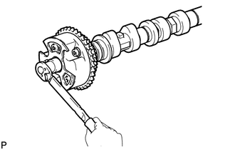
Install the flange bolt while holding the camshaft.
- Torque:
- 100 N*m (1020 kgf*cm, 74 ft.*lbf)
Check the lock of the camshaft timing gear assembly.
Fix the camshaft in place and confirm that the camshaft timing gear assembly is locked.
- NOTICE:
-
Be careful not to damage the camshaft.
13070A
4.INSTALL CAMSHAFT TIMING EXHAUST GEAR ASSEMBLY
- HINT:
-
for Automatic Transmission:
-
Perform "Inspection After Repairs" after replacing the camshaft timing exhaust gear assembly (See page Engine / Hybrid System>1GR-FE (ENGINE CONTROL)>SFI SYSTEM>INITIALIZATION).
Fix the camshaft in place.
- NOTICE:
-
Be careful not to damage the camshaft.
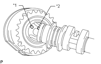
Put the camshaft timing exhaust gear assembly and camshaft together by aligning the pin hole and straight pin.
| *1 | Pin Hole |
| *2 | Straight Pin |
Lightly press and turn the camshaft timing gear assembly against the camshaft, and press harder after the pin enters the hole.
- NOTICE:
-
Be sure not to turn the camshaft timing exhaust gear in the advanced direction.
Check that there is no clearance between the gear flange and camshaft.
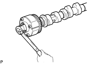
Install the flange bolt while holding the camshaft.
- Torque:
- 100 N*m (1020 kgf*cm, 74 ft.*lbf)
Check the camshaft timing exhaust gear lock.
Make sure that the camshaft timing exhaust gear assembly locks.
13053
5.INSTALL NO. 3 CAMSHAFT
- HINT:
-
for Automatic Transmission:
-
Perform "Inspection After Repairs" after replacing the No. 3 camshaft (See page Engine / Hybrid System>1GR-FE (ENGINE CONTROL)>SFI SYSTEM>INITIALIZATION).
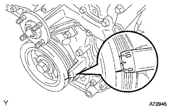
Check that the notch is aligned with the "0" timing mark of the timing chain cover.
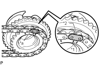
Align the mark plate (yellow) with the timing mark of the camshaft timing gear as shown in the illustration and install the No. 2 chain to the camshaft timing gear.
| *1 | Timing Mark |
| *2 | Mark Plate (yellow) |
| *a | Align |
Clean the camshaft housing LH and camshaft journals and apply engine oil to them.
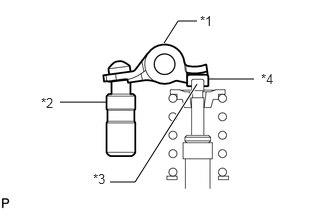
Make sure that the No. 1 valve rocker arm sub-assembly is installed as shown in the illustration.
| *1 | Valve Rocker Arm |
| *2 | Lash Adjuster |
| *3 | Valve Stem |
| *4 | Valve Stem Cap |
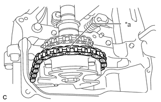
Install the chain to the No. 3 camshaft, and then install the camshaft to the camshaft housing LH.
| *a | Place on camshaft timing gear |
- HINT:
- ·
Place the chain on the camshaft timing gear but do not engage the teeth of the sprocket and the chain.
·Install the camshaft so that the timing mark is facing upward.
13054
6.INSTALL NO. 4 CAMSHAFT
- HINT:
-
for Automatic Transmission:
-
Perform "Inspection After Repairs" after replacing the No. 4 camshaft (See page Engine / Hybrid System>1GR-FE (ENGINE CONTROL)>SFI SYSTEM>INITIALIZATION).
Clean the camshaft housing LH and camshaft journals and apply engine oil to them.
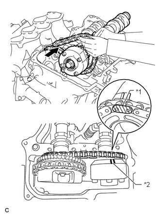
Pass the No. 4 camshaft through the No. 2 chain from the front of the vehicle, align the mark plate (yellow) with the timing mark and install the No. 2 chain to the camshaft timing exhaust gear.
| *1 | Mark Plate (yellow) |
| *2 | Timing Mark |
- HINT:
-
The mark plate is yellow.
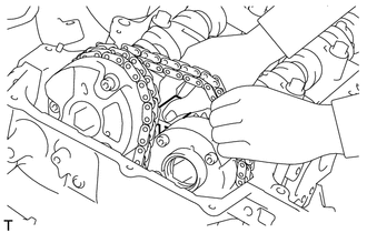
While lifting up the No. 4 camshaft, pass the No. 3 chain tensioner assembly through the No. 2 chain and set it in place.
Install the No. 4 camshaft to the camshaft housing LH, and then install the No. 3 chain tensioner assembly with the bolt.
- Torque:
- 21 N*m (214 kgf*cm, 15 ft.*lbf)
7.INSTALL CAMSHAFT BEARING CAP (for Bank 2)
Clean the camshaft bearing caps and apply engine oil to them.
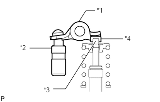
Make sure that the No. 1 valve rocker arm sub-assembly is installed as shown in the illustration.
| *1 | Valve Rocker Arm |
| *2 | Lash Adjuster |
| *3 | Valve Stem |
| *4 | Valve Stem Cap |
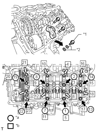
Check the marks and numbers on the camshaft bearing caps, and then remove the replacement bolts and washers in the order shown in the illustration. Immediately after removing the bolts and washers for temporary installation of the camshaft housing in the location for a bearing cap, install the bearing cap with the bolts in the order shown in the illustration.
- Torque:
- for bolt A : 28 N*m (286 kgf*cm, 21 ft.*lbf)
- for bolt B : 16 N*m (163 kgf*cm, 12 ft.*lbf)
| *1 | Bolt |
| *2 | Washer |
| *a | Installation of Bolts and Washers for Temporary Installation of camshaft housing |
| *b | Part Installation |

|
Bolt A |

|
Bolt B |
- NOTICE:
- ·
Be sure to follow the numerical order when performing this procedure.
·Do not drop bolts and washers for temporary installation of the camshaft housing into the cylinder head.
Check the torque of each bolt again.
13506
8.CONNECT CHAIN SUB-ASSEMBLY (for Bank 2)
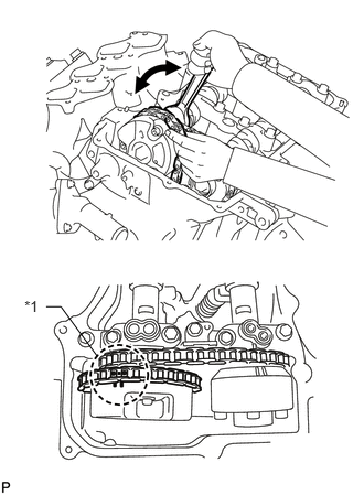
Align the paint marks on the camshaft timing gear and No. 1 chain and install the No. 1 chain to the camshaft timing gear.
| *1 | Paint Mark |
- HINT:
-
If the paint marks are not aligned, align them by turning the camshaft slightly.
13511
9.INSTALL CAMSHAFT
- HINT:
-
for Automatic Transmission:
-
Perform "Inspection After Repairs" after replacing the camshaft (See page Engine / Hybrid System>1GR-FE (ENGINE CONTROL)>SFI SYSTEM>INITIALIZATION).
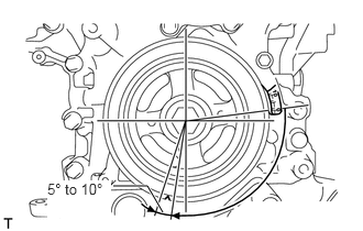
Turn the crankshaft clockwise until it is in the position shown in the illustration so that the chain can be installed easily.
- HINT:
-
When turning the crankshaft, engine oil may spray out of the oil holes.
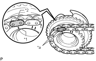
Align the mark plate (yellow) with the timing mark of the camshaft timing gear as shown in the illustration and install the No. 2 chain to the camshaft timing gear.
| *1 | Timing Mark |
| *2 | Mark Plate (yellow) |
| *a | Align |
Clean the camshaft housing RH and camshaft journals and apply engine oil to them.
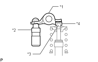
Make sure that the No. 1 valve rocker arm sub-assembly is installed as shown in the illustration.
| *1 | Valve Rocker Arm |
| *2 | Lash Adjuster |
| *3 | Valve Stem |
| *4 | Valve Stem Cap |
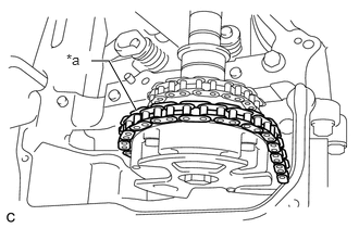
Install the chain to the camshaft, and then install the camshaft to the camshaft housing RH.
| *a | Place on camshaft timing gear |
- HINT:
- ·
Place the chain on the camshaft timing gear but do not engage the teeth of the sprocket and the chain.
·Install the camshaft so that the timing mark is facing upward.
13512
10.INSTALL NO. 2 CAMSHAFT
- HINT:
-
for Automatic Transmission:
-
Perform "Inspection After Repairs" after replacing the No. 2 camshaft (See page Engine / Hybrid System>1GR-FE (ENGINE CONTROL)>SFI SYSTEM>INITIALIZATION).
Clean the camshaft housing RH and camshaft journals and apply engine oil to them.
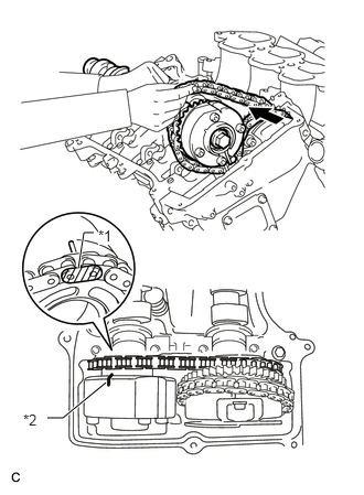
Pass the No. 2 camshaft through the No. 2 chain from the front of the vehicle, align the mark plate (yellow) with the timing mark and install the No. 2 chain to the camshaft timing exhaust gear.
| *1 | Mark Plate (yellow) |
| *2 | Timing Mark |
- HINT:
-
The mark plate is yellow.
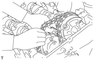
While lifting up the No. 2 camshaft, pass the No. 2 chain tensioner assembly through the No. 2 chain and set it in place.
Install the No. 2 camshaft to the camshaft housing RH, and then install the No. 2 chain tensioner assembly with the bolt.
- Torque:
- 21 N*m (214 kgf*cm, 15 ft.*lbf)
11.INSTALL CAMSHAFT BEARING CAP (for Bank 1)
Clean the camshaft bearing caps and apply engine oil to them.
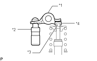
Make sure that the No. 1 valve rocker arm sub-assembly is installed as shown in the illustration.
| *1 | Valve Rocker Arm |
| *2 | Lash Adjuster |
| *3 | Valve Stem |
| *4 | Valve Stem Cap |
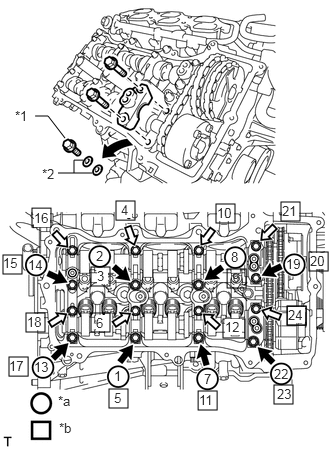
Check the marks and numbers on the camshaft bearing caps, and then remove the replacement bolts and washers in the order shown in the illustration. Immediately after removing the bolts and washers for temporary installation of the camshaft housing in the location for a bearing cap, install the bearing cap with the bolts in the order shown in the illustration.
- Torque:
- for bolt A : 28 N*m (286 kgf*cm, 21 ft.*lbf)
- for bolt B : 16 N*m (163 kgf*cm, 12 ft.*lbf)
| *1 | Bolt |
| *2 | Washer |
| *a | Installation of Bolts and Washers for Temporary Installation of camshaft housing |
| *b | Part Installation |
|
|
Bolt A |
|
|
Bolt B |
- NOTICE:
- ·
Be sure to follow the numerical order when performing this procedure.
·Do not drop bolts and washers for temporary installation of the camshaft housing into the cylinder head.
Check the torque of each bolt again.
13506
12.CONNECT CHAIN SUB-ASSEMBLY (for Bank 1)
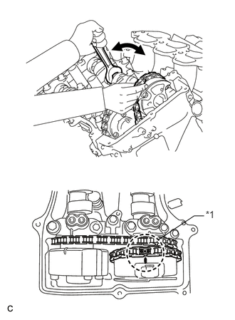
Align the paint marks on the camshaft timing gear and No. 1 chain and install the No. 1 chain to the camshaft timing gear.
| *1 | Paint Mark |
- HINT:
-
If the paint marks are not aligned, align them by turning the camshaft slightly.
13540
13.INSTALL NO. 1 CHAIN TENSIONER ASSEMBLY
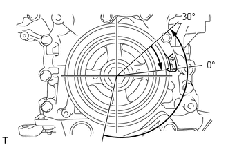
Turn the crankshaft counterclockwise 30° past the "0" timing mark, and then turn it clockwise to align the notch with the "0" timing mark.
Turn the crankshaft slightly to eliminate the slack in the chain.
- HINT:
-
Make sure there is some slack in the chain around the area where the chain tensioner is installed.
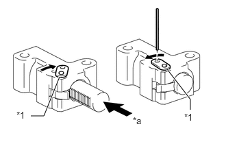
While turning the stopper plate of the tensioner clockwise, push in the plunger of the tensioner as shown in the illustration.
| *1 | Stopper Plate |
| *a | Push |
While turning the stopper plate of the tensioner counterclockwise, insert a pin of φ1.27 mm (0.0500 in.) into the holes in the stopper plate and tensioner to fix the stopper plate in place.
Install the chain tensioner with the 2 bolts.
- Torque:
- 10 N*m (102 kgf*cm, 7 ft.*lbf)
Remove the pin from the No. 1 chain tensioner.
14.INSPECT VALVE TIMING
Check the camshaft timing marks.
- NOTICE:
- ·
Check each timing mark from a viewpoint directly in line with the center of the camshaft and the timing mark on each camshaft timing gear.
·If the timing marks are checked from any other viewpoint, the valve timing may appear misaligned.
Check that each camshaft timing mark is positioned as shown in the illustration.
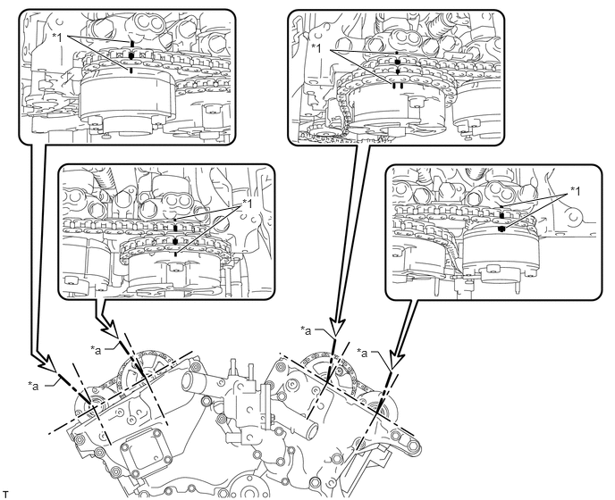
| *1 | Timing Mark | - | - |
| *a | Viewpoint | - | - |
- HINT:
-
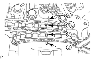 1.896,1.271 2.417,1.271 false 1.885,0.948 2.406,0.948 false 1.896,0.667 2.042,0.573 2.042,0.573 2.427,0.573 false 1.865,1.646 2.063,1.74 2.063,1.74 2.417,1.74 false 2.458,0.479 2.594,0.646 0.135,0.167 10 false A 2.469,0.875 2.604,1.042 0.135,0.167 10 false B 2.458,1.188 2.594,1.354 0.135,0.167 10 false C 2.469,1.667 2.604,1.833 0.135,0.167 10 false D
-
for Intake Camshaft:
-
Be sure to check mark A at the point when marks B, C and D are positioned in line. If the marks are checked from any other viewpoint, they cannot be checked correctly.
If the valve timing is misaligned, reinstall the timing chain.
Turn the crankshaft 2 revolutions, set the No. 1 cylinder to TDC/compression and check the timing marks again.
11324
15.INSTALL TIMING CHAIN COVER PLATE
Install a new gasket and the timing chain cover plate with the 4 bolts.
- Torque:
- 9.0 N*m (92 kgf*cm, 80 in.*lbf)
16.POUR ENGINE OIL
11201
17.INSTALL CYLINDER HEAD COVER SUB-ASSEMBLY
11202
18.INSTALL CYLINDER HEAD COVER SUB-ASSEMBLY LH
19.CONNECT FUEL PIPE SUB-ASSEMBLY
11181A
20.INSTALL REAR CYLINDER HEAD COVER
15772
21.INSTALL NO. 2 OIL PIPE
15771
22.INSTALL NO. 1 OIL PIPE
16206
23.INSTALL WATER BY-PASS PIPE SUB-ASSEMBLY (w/ Oil Cooler)
11452
24.INSTALL ENGINE OIL LEVEL DIPSTICK GUIDE
27020
25.INSTALL GENERATOR ASSEMBLY
17168
26.INSTALL NO. 2 EXHAUST MANIFOLD HEAT INSULATOR
82715
27.INSTALL WIRING HARNESS CLAMP BRACKET
16604
28.INSTALL NO. 2 IDLER PULLEY SUB-ASSEMBLY
44310
29.CONNECT VANE PUMP ASSEMBLY
19500
30.INSTALL IGNITION COIL ASSEMBLY
25702
31.INSTALL NO. 2 EMISSION CONTROL VALVE SET (w/ Secondary Air Injection System)
25701
32.INSTALL EMISSION CONTROL VALVE SET (w/ Secondary Air Injection System)
17362
33.INSTALL NO. 2 AIR TUBE (w/ Secondary Air Injection System)
17361
34.INSTALL AIR TUBE (w/ Secondary Air Injection System)
17129
35.INSTALL INTAKE AIR SURGE TANK
36.INSTALL AIR TUBE ASSEMBLY (w/ Secondary Air Injection System)
16711
37.INSTALL FAN SHROUD
32907C
38.CONNECT OIL COOLER TUBE (w/ Air Cooled Transmission Oil Cooler)
32907C
39.CONNECT OIL COOLER TUBE (w/ Warmer)
16470
40.INSTALL RADIATOR RESERVOIR
16572D
41.INSTALL NO. 2 RADIATOR HOSE
16571C
42.INSTALL NO. 1 RADIATOR HOSE
43.INSTALL AIR CLEANER CASE SUB-ASSEMBLY
44.INSTALL AIR CLEANER CAP AND HOSE
74431
45.INSTALL BATTERY TRAY
28800
46.INSTALL BATTERY
74481
47.INSTALL BATTERY HOLD DOWN CLAMP
28800A
48.CONNECT CABLE TO POSITIVE BATTERY TERMINAL
49.CONNECT CABLE TO NEGATIVE BATTERY TERMINAL
50. INITIALIZATION AFTER RECONNECTING BATTERY TERMINAL
- HINT:
-
When disconnecting and reconnecting the battery, there is an automatic learning function that completes learning when the respective system is used.
-
Click hereGeneral>SETUP>WHEN DISCONNECTING OR RECONNECTING BATTERY TERMINAL>AUTOMATIC LEARNING CHART
51.ADD ENGINE COOLANT
53.INSPECT FOR COOLANT LEAK
54.INSPECT FOR ENGINE OIL LEAK
11259
55.INSTALL V-BANK COVER
53292A
56.INSTALL UPPER RADIATOR SUPPORT SEAL
51405A
57.INSTALL NO. 1 ENGINE UNDER COVER SUB-ASSEMBLY
52129B
58.INSTALL FRONT BUMPER COVER LOWER
59.INSPECT IGNITION TIMING