1GR-FE INTAKE / EXHAUST EXHAUST MANIFOLD REMOVAL
PROCEDURE

 11259
1.REMOVE V-BANK COVER
2.REMOVE AIR CLEANER CAP AND HOSE
3.REMOVE AIR CLEANER CASE SUB-ASSEMBLY
53783
4.REMOVE FRONT FENDER APRON TRIM PACKING B
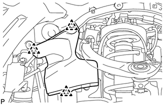
w/ KDSS:
Remove the 3 clips and front fender apron trim packing B.
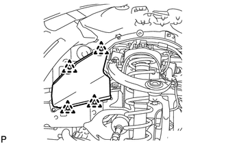
w/o KDSS:
Remove the 4 clips and front fender apron trim packing B.
53785B
5.REMOVE FRONT FENDER APRON TRIM PACKING D
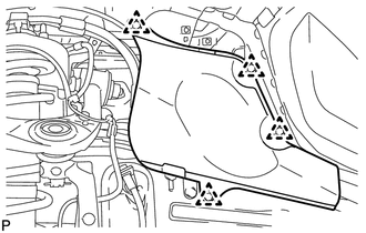
Remove the 4 clips and front fender apron trim packing D.
53782
6.REMOVE FRONT FENDER APRON TRIM PACKING A
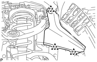
Remove the 3 clips and front fender apron trim packing A.
53784
7.REMOVE FRONT FENDER APRON TRIM PACKING C
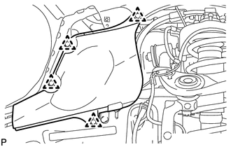
Remove the 4 clips and front fender apron trim packing C.
53806
8.REMOVE FRONT FENDER SPLASH SHIELD SUB-ASSEMBLY LH
53805
9.REMOVE FRONT FENDER SPLASH SHIELD SUB-ASSEMBLY RH
51405A
10.REMOVE NO. 1 ENGINE UNDER COVER SUB-ASSEMBLY
51442
11.REMOVE NO. 2 ENGINE UNDER COVER
17410
12.REMOVE FRONT EXHAUST PIPE ASSEMBLY
17118
13.REMOVE MANIFOLD STAY
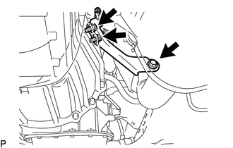
Remove the 3 bolts and manifold stay.
17361
14.REMOVE AIR TUBE (w/ Secondary Air Injection System)
45203A
15.DISCONNECT NO. 2 STEERING INTERMEDIATE SHAFT SUB-ASSEMBLY
for Manual Tilt and Manual Telescopic Steering Column: (See page Steering>STEERING COLUMN>STEERING COLUMN ASSEMBLY (for Manual Tilt and Manual Telescopic Steering Column)>REMOVAL)
for Power Tilt and Power Telescopic Steering Column: (See page Steering>STEERING COLUMN>STEERING COLUMN ASSEMBLY (for Power Tilt and Power Telescopic Steering Column)>REMOVAL)
17167
16.REMOVE NO. 1 EXHAUST MANIFOLD HEAT INSULATOR
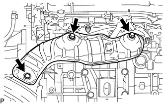
Remove the 3 bolts and heat insulator.
17104
17.REMOVE EXHAUST MANIFOLD SUB-ASSEMBLY RH
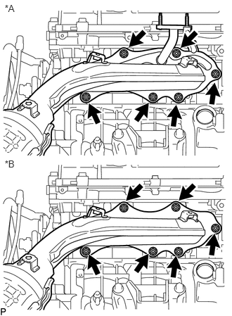
Disconnect the air fuel ratio sensor connector.
| *A | w/ Secondary Air Injection System |
| *B | w/o Secondary Air Injection System |
Remove the 6 nuts, exhaust manifold sub-assembly RH and gasket.
89467B
18.REMOVE AIR FUEL RATIO SENSOR (for Bank 1 Sensor 1)
17119
19.REMOVE NO. 2 MANIFOLD STAY
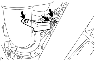
Remove the 3 bolts and No. 2 manifold stay.
17362
20.REMOVE NO. 2 AIR TUBE (w/ Secondary Air Injection System)
17168
21.REMOVE NO. 2 EXHAUST MANIFOLD HEAT INSULATOR
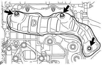
Remove the 3 bolts and heat insulator.
17105
22.REMOVE EXHAUST MANIFOLD SUB-ASSEMBLY LH
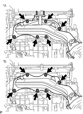
Disconnect the air fuel ratio sensor connector.
| *A | w/ Secondary Air Injection System |
| *B | w/o Secondary Air Injection System |
Remove the 6 nuts, exhaust manifold sub-assembly LH and gasket.
89467B
23.REMOVE AIR FUEL RATIO SENSOR (for Bank 2 Sensor 1)