LIGHTING (EXT) RELAY ON-VEHICLE INSPECTION
PROCEDURE

 85916N 1.INSPECT TAILLIGHT RELAY (for LHD)
Remove the front door scuff plate LH.
for 2 Door:
Click hereVehicle Interior>INTERIOR PANELS / TRIM>ROOF HEADLINING (for Single Cab)>REMOVAL
for 4 Door:
Click hereVehicle Interior>INTERIOR PANELS / TRIM>ROOF HEADLINING (for Double Cab)>REMOVAL
Remove the front floor footrest.
Click hereVehicle Interior>INTERIOR PANELS / TRIM>FRONT FLOOR FOOTREST(for LHD)>REMOVAL
Remove the cowl side trim sub-assembly LH.
Click hereVehicle Interior>INTERIOR PANELS / TRIM>ROOF HEADLINING (for Double Cab)>REMOVAL
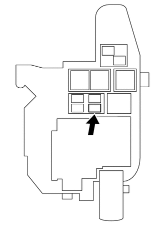
Remove the taillight relay (TAIL relay) from the cowl side relay block.
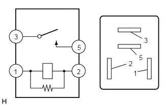
for 12 V Battery:
Inspect the taillight relay (TAIL relay).
Measure the resistance according to the value(s) in the table below.
- Standard Resistance:
-
Tester Connection Condition Specified Condition 3 - 5 Battery voltage is not applied to terminals 1 and 2 10 kΩ or higher Battery voltage is applied to terminals 1 and 2 Below 1 Ω
If the result is not as specified, replace the taillight relay (TAIL relay).
for 24 V Battery:
Inspect the taillight relay (TAIL relay).
Measure the resistance according to the value(s) in the table below.
- Standard Resistance:
-
Tester Connection Condition Specified Condition 3 - 5 Battery voltage is not applied to terminals 1 and 2 10 kΩ or higher Battery voltage is applied to terminals 1 and 2 Below 1 Ω
If the result is not as specified, replace the taillight relay (TAIL relay).
Install the taillight relay (TAIL relay) to the cowl side relay block.
Install the cowl side trim sub-assembly LH.
Click hereVehicle Interior>INTERIOR PANELS / TRIM>ROOF HEADLINING (for Double Cab)>INSTALLATION
Install the front floor footrest.
Click hereVehicle Interior>INTERIOR PANELS / TRIM>FRONT FLOOR FOOTREST(for LHD)>INSTALLATION
Install the front door scuff plate.
for 2 Door:
Click hereVehicle Interior>INTERIOR PANELS / TRIM>ROOF HEADLINING (for Single Cab)>INSTALLATION
for 4 Door:
Click hereVehicle Interior>INTERIOR PANELS / TRIM>ROOF HEADLINING (for Double Cab)>INSTALLATION
85916N 2.INSPECT TAILLIGHT RELAY (for RHD)
Remove the ECM.
for 1GR-FE:
Click hereEngine / Hybrid System>1GR-FE (ENGINE CONTROL)>ECM>REMOVAL
for 1VD-FTV:
Click hereEngine / Hybrid System>1VD-FTV (ENGINE CONTROL)>ECM>REMOVAL
Remove the front door scuff plate LH.
for 2 Door:
Click hereVehicle Interior>INTERIOR PANELS / TRIM>ROOF HEADLINING (for Single Cab)>REMOVAL
for 4 Door:
Click hereVehicle Interior>INTERIOR PANELS / TRIM>ROOF HEADLINING (for Double Cab)>REMOVAL
Remove the cowl side trim sub-assembly LH.
Click hereVehicle Interior>INTERIOR PANELS / TRIM>ROOF HEADLINING (for Double Cab)>REMOVAL
Remove the taillight relay (TAIL relay) from the cowl side relay block.
for 12 V Battery:
Inspect the taillight relay (TAIL relay).
Measure the resistance according to the value(s) in the table below.
- Standard Resistance:
-
Tester Connection Condition Specified Condition 3 - 5 Battery voltage is not applied to terminals 1 and 2 10 kΩ or higher Battery voltage is applied to terminals 1 and 2 Below 1 Ω
If the result is not as specified, replace the taillight relay (TAIL relay).
for 24 V Battery:
Inspect the taillight relay (TAIL relay).
Measure the resistance according to the value(s) in the table below.
- Standard Resistance:
-
Tester Connection Condition Specified Condition 3 - 5 Battery voltage is not applied to terminals 1 and 2 10 kΩ or higher Battery voltage is applied to terminals 1 and 2 Below 1 Ω
If the result is not as specified, replace the taillight relay (TAIL relay).
Install the taillight relay (TAIL relay) to the cowl side relay block.
Install the cowl side trim sub-assembly LH.
Click hereVehicle Interior>INTERIOR PANELS / TRIM>ROOF HEADLINING (for Double Cab)>INSTALLATION
Install the front door scuff plate LH.
for 2 Door:
Click hereVehicle Interior>INTERIOR PANELS / TRIM>ROOF HEADLINING (for Single Cab)>INSTALLATION
for 4 Door:
Click hereVehicle Interior>INTERIOR PANELS / TRIM>ROOF HEADLINING (for Double Cab)>INSTALLATION
Install the ECM.
for 1GR-FE:
Click hereEngine / Hybrid System>1GR-FE (ENGINE CONTROL)>ECM>INSTALLATION
for 1VD-FTV:
Click hereEngine / Hybrid System>1VD-FTV (ENGINE CONTROL)>ECM>INSTALLATION
85916P 3.INSPECT HEADLIGHT RELAY (for LHD)
Remove the front door scuff plate LH.
for 2 Door:
Click hereVehicle Interior>INTERIOR PANELS / TRIM>ROOF HEADLINING (for Single Cab)>REMOVAL
for 4 Door:
Click hereVehicle Interior>INTERIOR PANELS / TRIM>ROOF HEADLINING (for Double Cab)>REMOVAL
Remove the front floor footrest.
Click hereVehicle Interior>INTERIOR PANELS / TRIM>FRONT FLOOR FOOTREST(for LHD)>REMOVAL
Remove the cowl side trim sub-assembly LH.
Click hereVehicle Interior>INTERIOR PANELS / TRIM>ROOF HEADLINING (for Double Cab)>REMOVAL
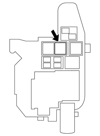
Remove the headlight relay (H-LP relay) from the cowl side relay block.
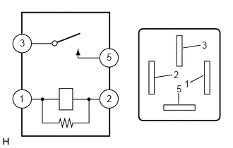
for 12 V Battery:
Inspect the headlight relay (H-LP relay).
Measure the resistance according to the value(s) in the table below.
- Standard Resistance:
-
Tester Connection Condition Specified Condition 3 - 5 Battery voltage is not applied to terminals 1 and 2 10 kΩ or higher Battery voltage is applied to terminals 1 and 2 Below 1 Ω
If the result is not as specified, replace the headlight relay (H-LP relay).
for 24 V Battery:
Inspect the headlight relay (H-LP relay).
Measure the resistance according to the value(s) in the table below.
- Standard Resistance:
-
Tester Connection Condition Specified Condition 3 - 5 Battery voltage is not applied to terminals 1 and 2 10 kΩ or higher Battery voltage is applied to terminals 1 and 2 Below 1 Ω
If the result is not as specified, replace the headlight relay (H-LP relay).
Install the headlight relay (H-LP relay) to the cowl side relay block.
Install the cowl side trim sub-assembly LH.
Click hereVehicle Interior>INTERIOR PANELS / TRIM>ROOF HEADLINING (for Double Cab)>INSTALLATION
Attach the 2 clips to install the front floor footrest.
Click hereVehicle Interior>INTERIOR PANELS / TRIM>FRONT FLOOR FOOTREST(for LHD)>INSTALLATION
Install the front door scuff plate LH.
for 2 Door:
Click hereVehicle Interior>INTERIOR PANELS / TRIM>ROOF HEADLINING (for Single Cab)>INSTALLATION
for 4 Door:
Click hereVehicle Interior>INTERIOR PANELS / TRIM>ROOF HEADLINING (for Double Cab)>INSTALLATION
85916P 4.INSPECT HEADLIGHT RELAY (for RHD)
Remove the ECM.
for 1GR-FE:
Click hereEngine / Hybrid System>1GR-FE (ENGINE CONTROL)>ECM>REMOVAL
for 1VD-FTV:
Click hereEngine / Hybrid System>1VD-FTV (ENGINE CONTROL)>ECM>REMOVAL
Remove the front door scuff plate LH.
for 2 Door:
Click hereVehicle Interior>INTERIOR PANELS / TRIM>ROOF HEADLINING (for Single Cab)>REMOVAL
for 4 Door:
Click hereVehicle Interior>INTERIOR PANELS / TRIM>ROOF HEADLINING (for Double Cab)>REMOVAL
Remove the cowl side trim sub-assembly LH.
Click hereVehicle Interior>INTERIOR PANELS / TRIM>ROOF HEADLINING (for Double Cab)>REMOVAL
Remove the headlight relay (H-LP relay) from the cowl side relay block.
for 12 V Battery:
Inspect the headlight relay (H-LP relay).
Measure the resistance according to the value(s) in the table below.
- Standard Resistance:
-
Tester Connection Condition Specified Condition 3 - 5 Battery voltage is not applied to terminals 1 and 2 10 kΩ or higher Battery voltage is applied to terminals 1 and 2 Below 1 Ω
If the result is not as specified, replace the headlight relay (H-LP relay).
for 24 V Battery:
Inspect the headlight relay (H-LP relay).
Measure the resistance according to the value(s) in the table below.
- Standard Resistance:
-
Tester Connection Condition Specified Condition 3 - 5 Battery voltage is not applied to terminals 1 and 2 10 kΩ or higher Battery voltage is applied to terminals 1 and 2 Below 1 Ω
If the result is not as specified, replace the headlight relay (H-LP relay).
Install the headlight relay (H-LP relay) to the cowl side relay block.
Install the cowl side trim sub-assembly LH.
Click hereVehicle Interior>INTERIOR PANELS / TRIM>ROOF HEADLINING (for Double Cab)>INSTALLATION
Install the front door scuff plate LH.
for 2 Door:
Click hereVehicle Interior>INTERIOR PANELS / TRIM>ROOF HEADLINING (for Single Cab)>INSTALLATION
for 4 Door:
Click hereVehicle Interior>INTERIOR PANELS / TRIM>ROOF HEADLINING (for Double Cab)>INSTALLATION
Install the ECM.
for 1GR-FE:
Click hereEngine / Hybrid System>1GR-FE (ENGINE CONTROL)>ECM>INSTALLATION
for 1VD-FTV:
Click hereEngine / Hybrid System>1VD-FTV (ENGINE CONTROL)>ECM>INSTALLATION
85926 5.INSPECT HEADLIGHT DIMMER RELAY (for LHD)
Remove the front door scuff plate LH.
for 2 Door:
Click hereVehicle Interior>INTERIOR PANELS / TRIM>ROOF HEADLINING (for Single Cab)>REMOVAL
for 4 Door:
Click hereVehicle Interior>INTERIOR PANELS / TRIM>ROOF HEADLINING (for Double Cab)>REMOVAL
Remove the front floor footrest.
Click hereVehicle Interior>INTERIOR PANELS / TRIM>FRONT FLOOR FOOTREST(for LHD)>REMOVAL
Remove the cowl side trim sub-assembly LH.
Click hereVehicle Interior>INTERIOR PANELS / TRIM>ROOF HEADLINING (for Double Cab)>REMOVAL
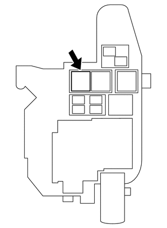
Remove the headlight dimmer relay (DIM relay) from the cowl side relay block.
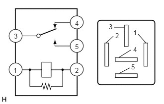
for 12 V Battery:
Inspect the headlight dimmer relay (DIM relay).
Measure the resistance according to the value(s) in the table below.
- Standard Resistance:
-
Tester Connection Condition Specified Condition 3 - 4 Battery voltage is not applied to terminals 1 and 2 Below 1 Ω Battery voltage is applied to terminals 1 and 2 10 kΩ or higher 3 - 5 Battery voltage is not applied to terminals 1 and 2 10 kΩ or higher Battery voltage is applied to terminals 1 and 2 Below 1 Ω
If the result is not as specified, replace the headlight dimmer relay (DIM relay).
for 24 V Battery:
Inspect the headlight dimmer relay (DIM relay).
Measure the resistance according to the value(s) in the table below.
- Standard Resistance:
-
Tester Connection Condition Specified Condition 3 - 4 Battery voltage is not applied to terminals 1 and 2 Below 1 Ω Battery voltage is applied to terminals 1 and 2 10 kΩ or higher 3 - 5 Battery voltage is not applied to terminals 1 and 2 10 kΩ or higher Battery voltage is applied to terminals 1 and 2 Below 1 Ω
If the result is not as specified, replace the headlight dimmer relay (DIM relay).
Install the headlight dimmer relay (DIM relay) to the cowl side relay block.
Install the cowl side trim sub-assembly LH.
Click hereVehicle Interior>INTERIOR PANELS / TRIM>ROOF HEADLINING (for Double Cab)>INSTALLATION
Install the front floor footrest.
Click hereVehicle Interior>INTERIOR PANELS / TRIM>FRONT FLOOR FOOTREST(for LHD)>INSTALLATION
Install the front door scuff plate LH.
for 2 Door:
Click hereVehicle Interior>INTERIOR PANELS / TRIM>ROOF HEADLINING (for Single Cab)>INSTALLATION
for 4 Door:
Click hereVehicle Interior>INTERIOR PANELS / TRIM>ROOF HEADLINING (for Double Cab)>INSTALLATION
85926 6.INSPECT HEADLIGHT DIMMER RELAY (for RHD)
Remove the ECM.
for 1GR-FE:
Click hereEngine / Hybrid System>1GR-FE (ENGINE CONTROL)>ECM>REMOVAL
for 1VD-FTV:
Click hereEngine / Hybrid System>1VD-FTV (ENGINE CONTROL)>ECM>REMOVAL
Remove the front door scuff plate LH.
for 2 Door:
Click hereVehicle Interior>INTERIOR PANELS / TRIM>ROOF HEADLINING (for Single Cab)>REMOVAL
for 4 Door:
Click hereVehicle Interior>INTERIOR PANELS / TRIM>ROOF HEADLINING (for Double Cab)>REMOVAL
Remove the cowl side trim sub-assembly LH.
Click hereVehicle Interior>INTERIOR PANELS / TRIM>ROOF HEADLINING (for Double Cab)>REMOVAL
Remove the headlight dimmer relay (DIM relay) from the cowl side relay block.
for 12 V Battery:
Inspect the headlight dimmer relay (DIM relay).
Measure the resistance according to the value(s) in the table below.
- Standard Resistance:
-
Tester Connection Condition Specified Condition 3 - 4 Battery voltage is not applied to terminals 1 and 2 Below 1 Ω Battery voltage is applied to terminals 1 and 2 10 kΩ or higher 3 - 5 Battery voltage is not applied to terminals 1 and 2 10 kΩ or higher Battery voltage is applied to terminals 1 and 2 Below 1 Ω
If the result is not as specified, replace the headlight dimmer relay (DIM relay).
for 24 V Battery:
Inspect the headlight dimmer relay (DIM relay).
Measure the resistance according to the value(s) in the table below.
- Standard Resistance:
-
Tester Connection Condition Specified Condition 3 - 4 Battery voltage is not applied to terminals 1 and 2 Below 1 Ω Battery voltage is applied to terminals 1 and 2 10 kΩ or higher 3 - 5 Battery voltage is not applied to terminals 1 and 2 10 kΩ or higher Battery voltage is applied to terminals 1 and 2 Below 1 Ω
If the result is not as specified, replace the headlight dimmer relay (DIM relay).
Install the headlight dimmer relay (DIM relay) to the cowl side relay block.
Install the cowl side trim sub-assembly LH.
Click hereVehicle Interior>INTERIOR PANELS / TRIM>ROOF HEADLINING (for Double Cab)>INSTALLATION
Install the front door scuff plate LH.
for 2 Door:
Click hereVehicle Interior>INTERIOR PANELS / TRIM>ROOF HEADLINING (for Single Cab)>INSTALLATION
for 4 Door:
Click hereVehicle Interior>INTERIOR PANELS / TRIM>ROOF HEADLINING (for Double Cab)>INSTALLATION
Install the ECM.
for 1GR-FE:
Click hereEngine / Hybrid System>1GR-FE (ENGINE CONTROL)>ECM>INSTALLATION
for 1VD-FTV:
Click hereEngine / Hybrid System>1VD-FTV (ENGINE CONTROL)>ECM>INSTALLATION
85916D 7.INSPECT FOG LIGHT RELAY (for LHD, w/ Fog Light)
Remove the front door scuff plate LH.
for 2 Door:
Click hereVehicle Interior>INTERIOR PANELS / TRIM>ROOF HEADLINING (for Single Cab)>REMOVAL
for 4 Door:
Click hereVehicle Interior>INTERIOR PANELS / TRIM>ROOF HEADLINING (for Double Cab)>REMOVAL
Remove the front floor footrest.
Click hereVehicle Interior>INTERIOR PANELS / TRIM>FRONT FLOOR FOOTREST(for LHD)>REMOVAL
Remove the cowl side trim sub-assembly LH.
Click hereVehicle Interior>INTERIOR PANELS / TRIM>ROOF HEADLINING (for Double Cab)>REMOVAL
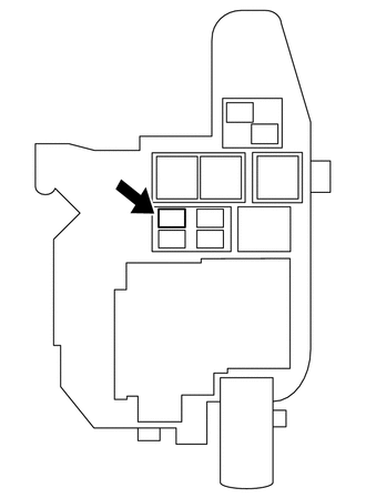
Remove the fog light relay (FR FOG relay) from the cowl side relay block.
Inspect the fog light relay (FR FOG relay).
Measure the resistance according to the value(s) in the table below.
- Standard Resistance:
-
Tester Connection Condition Specified Condition 3 - 5 Battery voltage is not applied to terminals 1 and 2 10 kΩ or higher Battery voltage is applied to terminals 1 and 2 Below 1 Ω
If the result is not as specified, replace the fog light relay (FR FOG relay).
Install the fog light relay (FR FOG relay) to the cowl side relay block.
Install the cowl side trim sub-assembly LH.
Click hereVehicle Interior>INTERIOR PANELS / TRIM>ROOF HEADLINING (for Double Cab)>INSTALLATION
Install the front floor footrest.
Click hereVehicle Interior>INTERIOR PANELS / TRIM>FRONT FLOOR FOOTREST(for LHD)>INSTALLATION
Install the front door scuff plate LH.
for 2 Door:
Click hereVehicle Interior>INTERIOR PANELS / TRIM>ROOF HEADLINING (for Single Cab)>INSTALLATION
for 4 Door:
Click hereVehicle Interior>INTERIOR PANELS / TRIM>ROOF HEADLINING (for Double Cab)>INSTALLATION
85916D 8.INSPECT FOG LIGHT RELAY (for RHD, w/ Fog Light)
Remove the ECM.
for 1GR-FE:
Click hereEngine / Hybrid System>1GR-FE (ENGINE CONTROL)>ECM>REMOVAL
for 1VD-FTV:
Click hereEngine / Hybrid System>1VD-FTV (ENGINE CONTROL)>ECM>REMOVAL
Remove the front door scuff plate LH.
for 2 Door:
Click hereVehicle Interior>INTERIOR PANELS / TRIM>ROOF HEADLINING (for Single Cab)>REMOVAL
for 4 Door:
Click hereVehicle Interior>INTERIOR PANELS / TRIM>ROOF HEADLINING (for Double Cab)>REMOVAL
Remove the cowl side trim sub-assembly LH.
Click hereVehicle Interior>INTERIOR PANELS / TRIM>ROOF HEADLINING (for Double Cab)>REMOVAL
Remove the fog light relay (FR FOG relay) from the cowl side relay block.
Inspect the fog light relay (FR FOG relay).
Measure the resistance according to the value(s) in the table below.
- Standard Resistance:
-
Tester Connection Condition Specified Condition 3 - 5 Battery voltage is not applied to terminals 1 and 2 10 kΩ or higher Battery voltage is applied to terminals 1 and 2 Below 1 Ω
If the result is not as specified, replace the fog light relay (FR FOG relay).
Install the fog light relay (FR FOG relay) to the cowl side relay block.
Install the cowl side trim sub-assembly LH.
Click hereVehicle Interior>INTERIOR PANELS / TRIM>ROOF HEADLINING (for Double Cab)>INSTALLATION
Install the front door scuff plate LH.
for 2 Door:
Click hereVehicle Interior>INTERIOR PANELS / TRIM>ROOF HEADLINING (for Single Cab)>INSTALLATION
for 4 Door:
Click hereVehicle Interior>INTERIOR PANELS / TRIM>ROOF HEADLINING (for Double Cab)>INSTALLATION
Install the ECM.
for 1GR-FE:
Click hereEngine / Hybrid System>1GR-FE (ENGINE CONTROL)>ECM>INSTALLATION
for 1VD-FTV:
Click hereEngine / Hybrid System>1VD-FTV (ENGINE CONTROL)>ECM>INSTALLATION
85916L 9.INSPECT REAR FOG LIGHT RELAY (w/ Rear Fog Light)
Remove the front door scuff plate LH.
for 2 Door:
Click hereVehicle Interior>INTERIOR PANELS / TRIM>ROOF HEADLINING (for Single Cab)>REMOVAL
for 4 Door:
Click hereVehicle Interior>INTERIOR PANELS / TRIM>ROOF HEADLINING (for Double Cab)>REMOVAL
Remove the front floor footrest.
Click hereVehicle Interior>INTERIOR PANELS / TRIM>FRONT FLOOR FOOTREST(for LHD)>REMOVAL
Remove the cowl side trim sub-assembly LH.
Click hereVehicle Interior>INTERIOR PANELS / TRIM>ROOF HEADLINING (for Double Cab)>REMOVAL
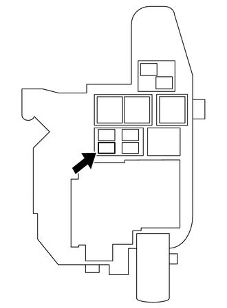
Remove the rear fog light relay (RR FOG relay) from the cowl side relay block.
Inspect the rear fog light relay (RR FOG relay).
Measure the resistance according to the value(s) in the table below.
- Standard Resistance:
-
Tester Connection Condition Specified Condition 3 - 5 Battery voltage is not applied to terminals 1 and 2 10 kΩ or higher Battery voltage is applied to terminals 1 and 2 Below 1 Ω
If the result is not as specified, replace the rear fog light relay (RR FOG relay).
Install the rear fog light relay (RR FOG relay) to the cowl side relay block.
Install the cowl side trim sub-assembly LH.
Click hereVehicle Interior>INTERIOR PANELS / TRIM>ROOF HEADLINING (for Double Cab)>INSTALLATION
Install the front floor footrest.
Click hereVehicle Interior>INTERIOR PANELS / TRIM>FRONT FLOOR FOOTREST(for LHD)>INSTALLATION
Install the front door scuff plate LH.
for 2 Door:
Click hereVehicle Interior>INTERIOR PANELS / TRIM>ROOF HEADLINING (for Single Cab)>INSTALLATION
for 4 Door:
Click hereVehicle Interior>INTERIOR PANELS / TRIM>ROOF HEADLINING (for Double Cab)>INSTALLATION
81990 10.INSPECT TURN SIGNAL RELAY ASSEMBLY (for 24 V Battery)
Remove the front door scuff plate LH.
Click hereVehicle Interior>INTERIOR PANELS / TRIM>ROOF HEADLINING (for Single Cab)>REMOVAL
Remove the cowl side trim sub-assembly LH.
Click hereVehicle Interior>INTERIOR PANELS / TRIM>ROOF HEADLINING (for Double Cab)>REMOVAL
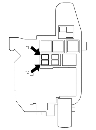
| *1 | FLSH Relay |
| *2 | FLSH 2 Relay |
Remove the turn signal relay assembly (FLSH relay or FLSH 2 relay) from the cowl side relay block.
for FLSH Relay:
Inspect the turn signal relay assembly (FLSH relay).
Measure the resistance according to the value(s) in the table below.
- Standard Resistance:
-
Tester Connection Condition Specified Condition 3 - 5 Battery voltage is not applied to terminals 1 and 2 10 kΩ or higher Battery voltage is applied to terminals 1 and 2 Below 1 Ω
If the result is not as specified, replace the turn signal relay assembly (FLSH relay).
for FLSH 2 Relay:
Inspect the turn signal relay assembly (FLSH 2 relay).
Measure the resistance according to the value(s) in the table below.
- Standard Resistance:
-
Tester Connection Condition Specified Condition 3 - 5 Battery voltage is not applied to terminals 1 and 2 10 kΩ or higher Battery voltage is applied to terminals 1 and 2 Below 1 Ω
If the result is not as specified, replace the turn signal relay assembly (FLSH 2 relay).
Install the turn signal relay assembly (FLSH relay or FLSH 2 relay) to the cowl side relay block.
Install the cowl side trim sub-assembly LH.
Click hereVehicle Interior>INTERIOR PANELS / TRIM>ROOF HEADLINING (for Double Cab)>INSTALLATION
Install the front door scuff plate LH.
Click hereVehicle Interior>INTERIOR PANELS / TRIM>ROOF HEADLINING (for Single Cab)>INSTALLATION