1VD-FTV ENGINE MECHANICAL ENGINE UNIT REMOVAL
PROCEDURE

 27280 1.REMOVE GENERATOR SPLASH GUARD COVER ASSEMBLY
27020 2.REMOVE GENERATOR ASSEMBLY
44774 3.DISCONNECT UNION TO CONNECTOR TUBE HOSE
29300 4.REMOVE VACUUM PUMP ASSEMBLY
15301 5.REMOVE ENGINE OIL LEVEL DIPSTICK
12142 6.REMOVE NO. 2 ENGINE OIL LEVEL DIPSTICK GUIDE
11452 7.REMOVE ENGINE OIL LEVEL DIPSTICK GUIDE
17167 8.REMOVE NO. 1 EXHAUST MANIFOLD HEAT INSULATOR
17168 9.REMOVE NO. 2 EXHAUST MANIFOLD HEAT INSULATOR
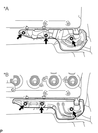
| *A | w/ DPF |
| *B | w/o DPF |
Remove the 3 bolts and No. 2 exhaust manifold heat insulator.
17106 10.REMOVE EXHAUST CROSSOVER PIPE SUB-ASSEMBLY
17118 11.REMOVE MANIFOLD STAY
17119 12.REMOVE NO. 2 MANIFOLD STAY
17141 13.REMOVE EXHAUST MANIFOLD RH
15407 14.DISCONNECT TURBO OIL INLET PIPE SUB-ASSEMBLY
15474A 15.REMOVE TURBO OIL OUTLET HOSE
17192 16.REMOVE NO. 2 EXHAUST MANIFOLD PIPE (w/ DPF)
17293 17.REMOVE TURBOCHARGER STAY
17361J 18.REMOVE NO. 1 AIR TUBE
16027 19.REMOVE NO. 1 TURBO WATER PIPE SUB-ASSEMBLY
17878 20.REMOVE NO. 3 INTAKE AIR CONNECTOR PIPE
17142 21.REMOVE EXHAUST MANIFOLD LH WITH TURBOCHARGER SUB-ASSEMBLY
16630H 22.REMOVE IDLER PULLEY ASSEMBLY (w/o Air Conditioning System)
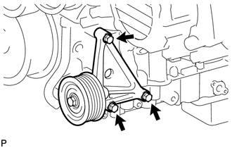
Remove the 3 bolts and idler pulley assembly.
25708 23.REMOVE NO. 3 VACUUM TRANSMITTING PIPE SUB-ASSEMBLY
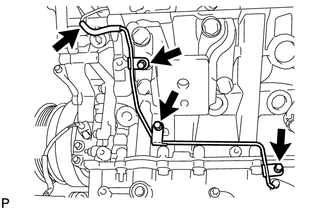
Disconnect the vacuum hose from the No. 2 vacuum transmitting pipe.
Remove the 3 bolts and No. 3 vacuum transmitting pipe sub-assembly.
12325A 24.REMOVE TRANSVERSE ENGINE MOUNTING BRACKET LH
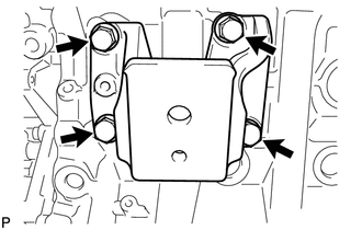
Remove the 4 bolts and transverse engine mounting bracket LH.
12315A 25.REMOVE TRANSVERSE ENGINE MOUNTING BRACKET RH
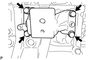
Remove the 4 bolts and transverse engine mounting bracket RH.
16283 26.REMOVE NO. 6 WATER BY-PASS HOSE (w/o DPF)
23764A 27.REMOVE NO. 4 NOZZLE LEAKAGE PIPE (w/o DPF)
23763 28.DISCONNECT NO. 3 NOZZLE LEAKAGE PIPE (w/o DPF)
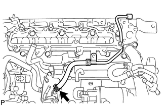
Slide the clamp and disconnect the No. 1 fuel hose from the fuel cooler assembly.
23920A 29.REMOVE FUEL COOLER ASSEMBLY (w/o DPF)
16283 30.REMOVE NO. 6 WATER BY-PASS HOSE (w/ DPF)
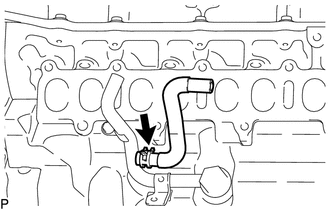
Slide the clamp and remove the No. 6 water by-pass hose from the No. 1 water by-pass pipe.
16268 31.REMOVE NO. 1 WATER BY-PASS PIPE
17111 32.REMOVE INTAKE MANIFOLD
17112 33.REMOVE NO. 2 INTAKE MANIFOLD
28100 34.REMOVE STARTER ASSEMBLY
35.REMOVE STARTER HOSE BRACKET SUB-ASSEMBLY
19850 36.REMOVE GLOW PLUG ASSEMBLY
17946 37.REMOVE NO. 2 INTERCOOLER SUPPORT BRACKET
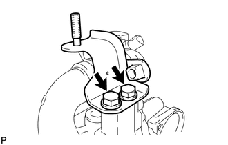
Remove the 2 bolts and No. 2 intercooler support bracket.
17945 38.REMOVE INTERCOOLER SUPPORT BRACKET
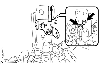
Remove the 2 bolts and intercooler support bracket.
39.REMOVE NO. 3 ENGINE HANGER
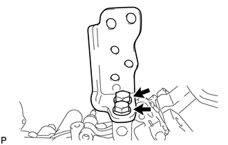
Remove the 2 bolts and No. 3 engine hanger.
15409F 40.REMOVE OIL FILTER OUTLET PIPE SUB-ASSEMBLY
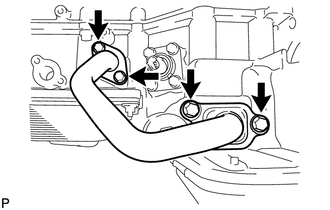
Remove the 4 bolts and oil filter outlet pipe sub-assembly.
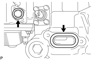
Remove the 2 gaskets.
89422C 41.REMOVE ENGINE COOLANT TEMPERATURE SENSOR
16331 42.REMOVE WATER OUTLET
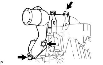
Remove the 2 bolts and disconnect the water outlet and gasket.
Slide the clamp and disconnect the No. 2 water hose joint from the No. 1 water outlet pipe.
43.REMOVE WATER OUTLET PIPE
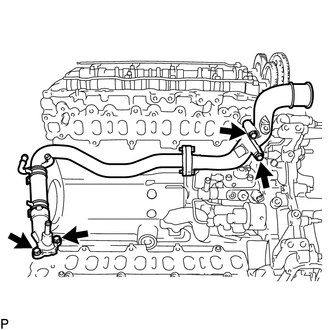
w/ DPF:
Remove the 4 bolts, water outlet pipe and 2 gaskets.
w/o DPF:
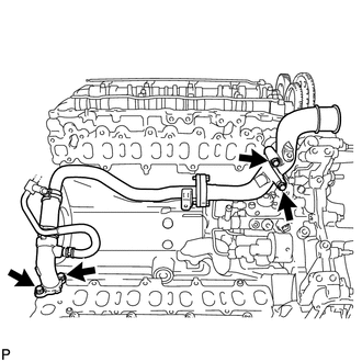
Remove the 4 bolts, water outlet pipe and 2 gaskets.
16332 44.SEPARATE NO. 1 AND NO. 2 WATER OUTLET PIPES AND WATER BY-PASS OUTLET SUB-ASSEMBLY
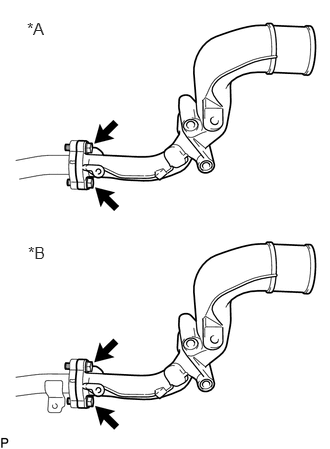
| *A | w/ DPF |
| *B | w/o DPF |
Remove the 2 bolts and No. 1 water outlet pipe from the No. 2 water outlet pipe.
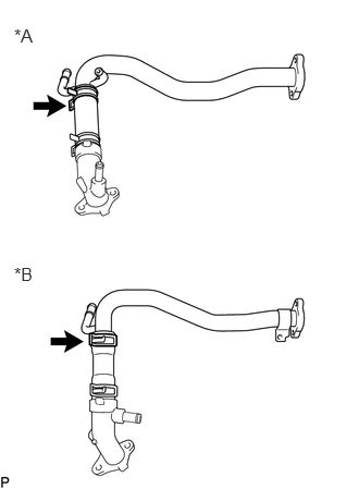
| *A | w/ DPF |
| *B | w/o DPF |
Slide the clamp and remove the water hose joint from the water by-pass outlet sub-assembly.
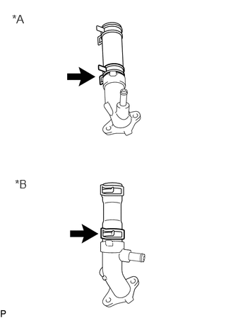
| *A | w/ DPF |
| *B | w/o DPF |
Slide the clamp and remove the water hose joint from the water by-pass outlet sub-assembly.
16307A 45.REMOVE FAN BRACKET SUB-ASSEMBLY
16603B 46.REMOVE IDLER PULLEY SUB-ASSEMBLY
16620D 47.REMOVE V-RIBBED BELT TENSIONER ASSEMBLY
16321 48.REMOVE WATER INLET
16331A 49.REMOVE THERMOSTAT
16262 50.DISCONNECT WATER INLET HOSE
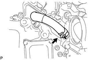
Slide the clamp and disconnect the water inlet hose from the timing chain cover sub-assembly.
51.SET NO. 1 CYLINDER TO TDC/COMPRESSION
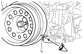
| *a | Timing Mark |
Align the timing mark of the crankshaft pulley and timing chain cover sub-assembly and chain cover and compressor bracket sub-assembly.
12502 52.REMOVE CHAIN COVER AND COMPRESSOR BRACKET SUB-ASSEMBLY
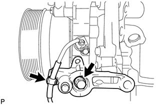
Detach the wire harness clamp.
Remove the bolt and the chain cover and compressor bracket sub-assembly.
53.REMOVE ENGINE WIRE BRACKET
89491 54.REMOVE ENGINE OIL LEVEL SENSOR
55.REMOVE INJECTOR LEAD WIRE (w/ DPF)
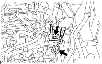
Disconnect the exhaust fuel addition injector assembly connector.
Remove the bolt and injector lead wire.
23710B 56.REMOVE EXHAUST FUEL ADDITION INJECTOR ASSEMBLY (w/ DPF)
23255B 57.REMOVE FUEL INJECTOR SEAL (w/ DPF)
11459 58.REMOVE ENGINE OIL LEVEL DIPSTICK GUIDE SUPPORT (w/ DPF)
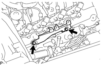
Remove the 2 bolts and engine oil level dipstick guide support.