1VD-FTV INTAKE / EXHAUST EXHAUST MANIFOLD W/ TURBOCHARGER(w/o DPF) INSTALLATION
PROCEDURE

 1.INSTALL STUD BOLT
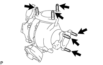
Using an E10 "TORX" socket wrench, install the 6 stud bolts to the turbocharger sub-assembly.
- Torque:
- 20 N*m (204 kgf*cm, 15 ft.*lbf)
17274 2.INSTALL INLET COMPRESSOR ELBOW
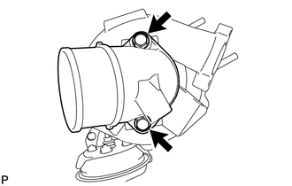
Install a new gasket and the inlet compressor elbow to the turbocharger sub-assembly with the 2 bolts.
- Torque:
- 21 N*m (214 kgf*cm, 15 ft.*lbf)
15481 3.INSTALL NO. 1 TURBO OIL PIPE
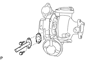
Install a new gasket and the No. 1 turbo oil pipe to the turbocharger sub-assembly with the 2 bolts.
- Torque:
- 10 N*m (102 kgf*cm, 7 ft.*lbf)
- HINT:
-
Install the gasket with the gasket's claws facing the No. 1 turbo oil pipe.
15407 4.INSTALL INLET TURBO OIL PIPE SUB-ASSEMBLY
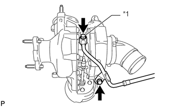
| *1 | Union Bolt |
Install a new gasket and the union bolt.
- Torque:
- 24 N*m (245 kgf*cm, 18 ft.*lbf)
Install the inlet turbo oil pipe sub-assembly to the turbocharger sub-assembly with the bolt.
- Torque:
- 10 N*m (102 kgf*cm, 7 ft.*lbf)
17141 5.INSTALL EXHAUST MANIFOLD RH
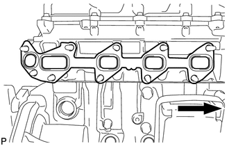

|
Front |
Install a new gasket to the cylinder head sub-assembly RH.
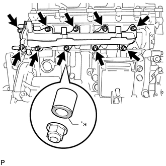
| *a | Colored Side |
Install the exhaust manifold RH and 10 collars with 10 new nuts.
- Torque:
- 36 N*m (367 kgf*cm, 27 ft.*lbf)
- NOTICE:
-
Install the collars with the collars' colored side facing the nuts.
17142 6.INSTALL EXHAUST MANIFOLD LH
Install a new gasket and the turbocharger sub-assembly to the exhaust manifold LH with 3 new nuts.
- Torque:
- 69 N*m (704 kgf*cm, 51 ft.*lbf)
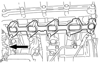
|
|
Front |
Set a new gasket to the cylinder head sub-assembly LH.
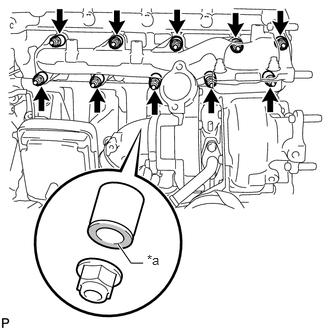
| *a | Colored Side |
Install the exhaust manifold LH with turbocharger sub-assembly with 10 new nuts and the 10 collars.
- Torque:
- 36 N*m (367 kgf*cm, 27 ft.*lbf)
- NOTICE:
-
Install the collars with the collars' colored side facing the nuts.
17293 7.INSTALL TURBOCHARGER STAY
17106 8.INSTALL EXHAUST CROSSOVER PIPE SUB-ASSEMBLY
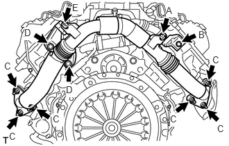
Temporarily install the No. 1 and No. 2 manifold stays to the exhaust crossover pipe sub-assembly with the 2 bolts labeled A and E shown in the illustration.
- HINT:
-
Make sure the manifold stays and exhaust crossover pipe sub-assembly are contacting each other.
Install a new gasket to the exhaust manifold RH and a new gasket to the exhaust manifold LH.
Temporarily install the exhaust crossover pipe sub-assembly with the bolt labeled B, 6 nuts labeled C, and 2 bolts labeled D.
- HINT:
-
Make sure to tighten the nuts labeled C so that the exhaust crossover pipe sub-assembly and exhaust manifold are contacting each other.
Tighten the bolt labeled B.
- Torque:
- 43 N*m (438 kgf*cm, 32 ft.*lbf)
Tighten the bolts labeled D.
- Torque:
- 50 N*m (510 kgf*cm, 37 ft.*lbf)
Tighten the nuts labeled C.
- Torque:
- 69 N*m (704 kgf*cm, 51 ft.*lbf)
Tighten the bolt labeled A.
- Torque:
- 43 N*m (438 kgf*cm, 32 ft.*lbf)
Tighten the bolt labeled E.
- Torque:
- 50 N*m (510 kgf*cm, 37 ft.*lbf)
9.CONNECT MANUAL TRANSMISSION WITH TRANSFER
12101 10.CHECK OIL PAN SUB-ASSEMBLY
12101 11.INSTALL OIL PAN SUB-ASSEMBLY
12.INSTALL OIL FILTER ELEMENT
15614 13.INSTALL LOWER OIL FILTER ELEMENT COVER
12102A 14.CHECK NO. 2 OIL PAN SUB-ASSEMBLY
12102A 15.INSTALL NO. 2 OIL PAN SUB-ASSEMBLY
12140 16.INSTALL OIL PAN COVER
12201 17.INSTALL VENTILATION TUBE SUB-ASSEMBLY
25708 18.INSTALL NO. 3 VACUUM TRANSMITTING PIPE SUB-ASSEMBLY
15474A 19.INSTALL OUTLET TURBO OIL HOSE
20.INSTALL ENGINE WIRE BRACKET
83520 21.INSTALL OIL PRESSURE SENDER GAUGE ASSEMBLY
15407 22.CONNECT INLET TURBO OIL PIPE SUB-ASSEMBLY
15769 23.CONNECT OIL COOLER PIPE
24.CONNECT ENGINE WIRE
16027 25.INSTALL NO. 1 TURBO WATER PIPE SUB-ASSEMBLY
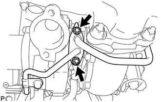
Install a new gasket and the No. 1 turbo water pipe sub-assembly to the turbocharger sub-assembly with 2 new nuts.
- Torque:
- 10 N*m (102 kgf*cm, 7 ft.*lbf)
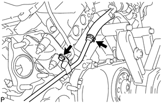
Install the bolt.
- Torque:
- 10 N*m (102 kgf*cm, 7 ft.*lbf)
Connect the No. 2 turbo water hose from the No. 1 turbo water pipe sub-assembly, and slide the clip to secure the hose.
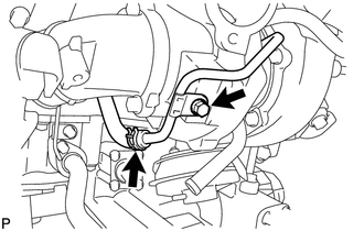
Install the bolt.
- Torque:
- 10 N*m (102 kgf*cm, 7 ft.*lbf)
Connect the No. 1 turbo water hose from the No. 1 turbo water pipe sub-assembly, and slide the clip to secure the hose.
17361J 26.INSTALL NO. 1 AIR TUBE
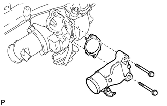
Install a new gasket and the No. 1 air tube with the 2 bolts.
- Torque:
- 21 N*m (214 kgf*cm, 15 ft.*lbf)
- HINT:
-
Install the gasket with the gasket's claws facing the turbocharger sub-assembly.
17343D 27.INSTALL NO. 3 AIR HOSE
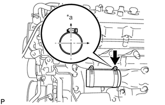
| *a | Upper |
Install the No. 3 air hose to the turbocharger sub-assembly with the clamp.
- Torque:
- 6.3 N*m (64 kgf*cm, 56 in.*lbf)
- HINT:
-
Install the clamp as shown in the illustration.
17362B 28.INSTALL NO. 2 AIR TUBE
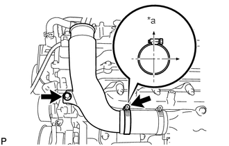
| *a | Upper |
Connect the No. 2 air tube to the No. 3 air hose with the 2 clamps.
- Torque:
- 6.3 N*m (64 kgf*cm, 56 in.*lbf)
- HINT:
-
Install the clamp as shown in the illustration.
Install the No. 2 air tube with the bolt.
- Torque:
- 21 N*m (214 kgf*cm, 15 ft.*lbf)
17878 29.INSTALL NO. 3 INTAKE AIR CONNECTOR PIPE
16620D 30.INSTALL V-RIBBED BELT TENSIONER ASSEMBLY
16603B 31.INSTALL IDLER PULLEY SUB-ASSEMBLY
15778 32.CONNECT NO. 2 OIL COOLER HOSE
27020 33.INSTALL GENERATOR ASSEMBLY
27280 34.INSTALL GENERATOR SPLASH GUARD COVER ASSEMBLY
16400 35.INSTALL RADIATOR ASSEMBLY
16572D 36.CONNECT NO. 2 RADIATOR HOSE
16371 37.INSTALL FAN PULLEY
16711 38.INSTALL FAN SHROUD
16470 39.INSTALL RADIATOR RESERVOIR ASSEMBLY
16361A 40.INSTALL FAN AND GENERATOR V-RIBBED BELT
17875 41.INSTALL INTAKE AIR CONNECTOR PIPE
42.INSTALL INTAKE AIR CONNECTOR ASSEMBLY
43.INSTALL AIR CLEANER CASE SUB-ASSEMBLY
17705 44.INSTALL AIR CLEANER CAP SUB-ASSEMBLY
Install the air cleaner filter element sub-assembly to the air cleaner case sub-assembly.
Attach the 4 clamps to install the air cleaner cap sub-assembly to the air cleaner case sub-assembly.
17881 45.INSTALL NO. 1 AIR CLEANER HOSE
17167 46.INSTALL NO. 1 EXHAUST MANIFOLD HEAT INSULATOR
Install the No. 1 exhaust manifold heat insulator with the 3 bolts.
- Torque:
- 25 N*m (255 kgf*cm, 18 ft.*lbf)
17168 47.INSTALL NO. 2 EXHAUST MANIFOLD HEAT INSULATOR
Install the No. 2 exhaust manifold heat insulator with the 3 bolts.
- Torque:
- 25 N*m (255 kgf*cm, 18 ft.*lbf)
w/ Air Conditioning System:
Install the No. 1 fuel tube bracket with the 2 bolts.
Attach the clamp.
- Torque:
- 5.4 N*m (55 kgf*cm, 48 in.*lbf)
Install the fuel tube bracket with the bolt.
- Torque:
- 5.4 N*m (55 kgf*cm, 48 in.*lbf)
Attach the engine wire.
48.INSTALL TUBE SUB-ASSEMBLY (w/ Air Conditioning System)
16571C 49.INSTALL NO. 1 RADIATOR HOSE
50.INSTALL HEATER WATER VALVE ASSEMBLY
17940D 51.INSTALL INTERCOOLER ASSEMBLY
17341F 52.INSTALL NO. 1 AIR HOSE
87249B 53.CONNECT OUTLET HEATER WATER PIPE B
18450A 54.INSTALL MONOLITHIC CONVERTER ASSEMBLY
Temporarily install a new gasket to the monolithic converter assembly by hand.
- HINT:
-
Be sure to install the gasket as evenly as possible.
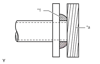
| *1 | Gasket |
| *a | Wooden Block |
Using a plastic-faced hammer and wooden block, tap the gasket onto the monolithic converter assembly so that the gasket is flush with the pipe end.
- NOTICE:
-
·
Install the gasket in the correct direction.
·Do not damage the outer surface of the gasket.
·Do not reuse the gasket.
·Do not push in the gasket with the exhaust pipe when connecting it.
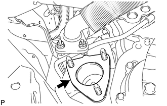
Install a new gasket onto the outlet turbine elbow.
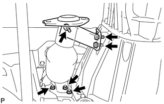
Loosely install the monolithic converter assembly with 3 new nuts.
- HINT:
-
Tighten the nuts until the contact surface of the monolithic converter assembly contacts with the outlet turbine elbow.
Loosely install the center converter protector stay with the 3 bolts.
- HINT:
-
Tighten the bolts so that the position of the monolithic converter assembly can be adjusted in a later step.
Tighten the 3 nuts of the monolithic converter assembly.
- Torque:
- 47 N*m (479 kgf*cm, 35 ft.*lbf)
Tighten the 3 bolts of the center converter protector stay.
- Torque:
- 43 N*m (438 kgf*cm, 32 ft.*lbf)
Inspect the compression spring.
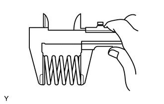
Using a vernier caliper, measure the free length of the compression spring.
- Standard free length:
-
43 mm (1.69 in.)
If the free length is not as specified, replace the compression spring.
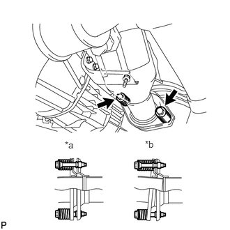
| *a | CORRECT |
| *b | INCORRECT |
Connect the monolithic converter assembly to the front exhaust pipe assembly with the 2 bolts and 2 compression springs.
- Torque:
- 43 N*m (438 kgf*cm, 32 ft.*lbf)
- NOTICE:
-
·
When tightening the bolts, make sure the lengths of the springs are approximately the same.
·Make sure the joint part is movable.
·Make sure the bolts do not get caught on the flange.
11452 55.INSTALL NO. 1 ENGINE OIL LEVEL DIPSTICK GUIDE
12142 56.INSTALL NO. 2 ENGINE OIL LEVEL DIPSTICK GUIDE
57.INSTALL ENGINE OIL LEVEL DIPSTICK
58.ADD ENGINE OIL
59.ADD ENGINE COOLANT
60.CONNECT CABLE TO NEGATIVE BATTERY TERMINAL
61. INITIALIZATION AFTER RECONNECTING BATTERY TERMINAL
- HINT:
-
When disconnecting and reconnecting the battery, there is an automatic learning function that completes learning when the respective system is used.
-
Click hereGeneral>SETUP>WHEN DISCONNECTING OR RECONNECTING BATTERY TERMINAL>AUTOMATIC LEARNING CHART
62.INSPECT FOR OIL LEAK
63.INSPECT FOR COOLANT LEAK
64. CHECK ENGINE OIL LEVEL
65.INSPECT FOR EXHAUST GAS LEAK
If gas is leaking, tighten the areas necessary to stop the leak. Replace damaged parts as necessary.
51442 66.INSTALL NO. 2 ENGINE UNDER COVER
53737B 67.INSTALL FRONT FENDER APRON SEAL LH
Install the front fender apron seal LH with the 11 clips.
53736 68.INSTALL FRONT FENDER APRON SEAL RH
Install the front fender apron seal RH with the 11 clips.
69.CHARGE AIR CONDITIONING SYSTEM WITH REFRIGERANT
70.WARM UP ENGINE
71.CHECK FOR REFRIGERANT GAS LEAK