HYBRID / BATTERY CONTROL FUSE BOX REMOVAL
CAUTION / NOTICE / HINT
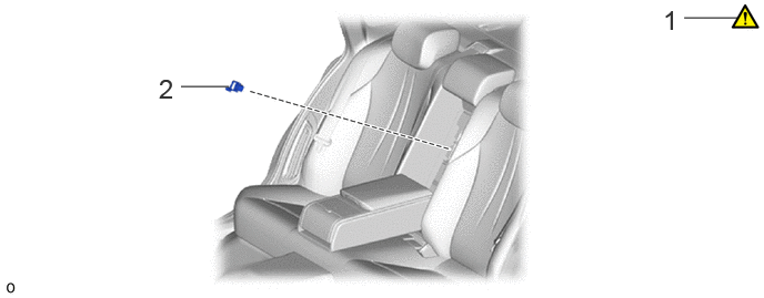
| Procedure | Part Name Code | 
|

|

|
|
|---|---|---|---|---|---|
| 1 | PRECAUTION | - | ( ) |
- | - |
| 2 | SERVICE PLUG GRIP | G3834 | - | - | - |
| Procedure | Part Name Code |
|
|
|
|
|---|---|---|---|---|---|
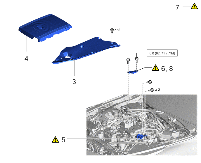
| 3 | UPPER RADIATOR SUPPORT SEAL | 53292A | - | - | - |
| 4 | FC STACK COVER SUB-ASSEMBLY | 1A906 | - | - | - |
| 5 | FC CONVERTER POWER OUTLET CABLE (INVERTER WITH CONVERTER ASSEMBLY) | G9200A | ()
|
- | - |
| 6 | REMOVE CONNECTOR COVER ASSEMBLY | - | ()
|
- | - |
| 7 | CHECK TERMINAL VOLTAGE | - | ()
|
- | - |
| 8 | INSTALL CONNECTOR COVER ASSEMBLY | - | ()
|
- | - |

|
N*m (kgf*cm, ft.*lbf): Specified torque | - | - |
| Procedure | Part Name Code |
|
|
|
|
|---|---|---|---|---|---|
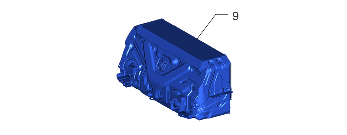
| 9 | EV SUPPLY BATTERY ASSEMBLY | G9510B | - | - | - |
| Procedure | Part Name Code |
|
|
|
|
|---|---|---|---|---|---|
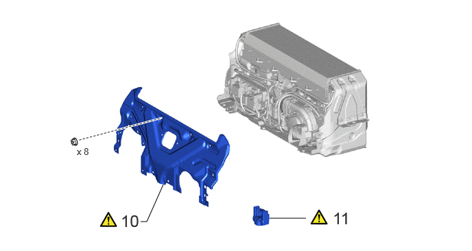
| 10 | UPPER EV BATTERY COVER PANEL | G92N1B | ()
|
- | - |
| 11 | EV BATTERY TERMINAL BLOCK | G92Z2A | ()
|
- | - |
CAUTION / NOTICE / HINT
The necessary procedures (adjustment, calibration, initialization, or registration) that must be performed after parts are removed and installed, or replaced during EV battery terminal block removal/installation are shown below.
| Replacement Part or Procedure | Necessary Procedure | Effect/Inoperative when not Performed | Link |
|---|---|---|---|
| Disconnect cable from negative auxiliary battery terminal | Memorize steering angle neutral point | Parking assist monitor system | ()
|
| Panoramic view monitor system | ()
|
||
| EV battery terminal block | Perform high voltage fuse accumulated load history reset | DTCs are output | ()
|
- CAUTION:
- ·
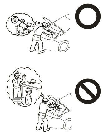
·Orange wire harnesses and connectors indicate high-voltage circuits. To prevent electric shock, always follow the procedure described in the repair manual.
Click hereEngine / Hybrid System>HYBRID / BATTERY CONTROL>HYBRID CONTROL SYSTEM>PRECAUTION
·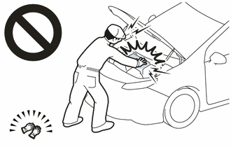
To prevent electric shock, wear insulated gloves when working on wire harnesses and components of the high voltage system.
- HINT:
-
When the cable is disconnected/reconnected to the auxiliary battery terminal, systems temporarily stop operating. However, each system has a function that completes learning the first time the system is used.
- ·
Learning completes when vehicle is driven
Effect/Inoperative Function When Necessary Procedures are not Performed Necessary Procedures Link Lane tracing assist system Drive the vehicle straight ahead at 35 km/h (22 mph) or more for 5 seconds or more. ( )
Pre-collision system Adaptive high beam system
- ·
Learning completes when vehicle is operated normally
Effect/Inoperative Function When Necessary Procedures are not Performed Necessary Procedures Link Air conditioning system After the ignition switch is turned to ON, the servo motor and expansion valve standard position is recognized. -
PROCEDURE

 1. PRECAUTION
|
|
Click here()
|
G3834
2.REMOVE SERVICE PLUG GRIP
53292A
3.REMOVE UPPER RADIATOR SUPPORT SEAL
1A906
4.REMOVE FC STACK COVER SUB-ASSEMBLY
G9200A
5.DISCONNECT FC CONVERTER POWER OUTLET CABLE (INVERTER WITH CONVERTER ASSEMBLY)
|
|
Click here()
|
6.REMOVE CONNECTOR COVER ASSEMBLY
|
|
Click here()
|
7.CHECK TERMINAL VOLTAGE
|
|
Click here()
|
8.INSTALL CONNECTOR COVER ASSEMBLY
|
|
Click here()
|
G9510B
9.REMOVE EV SUPPLY BATTERY ASSEMBLY
G92N1B
10.REMOVE UPPER EV BATTERY COVER PANEL
|
|
Click here()
|
G92Z2A
11.REMOVE EV BATTERY TERMINAL BLOCK
|
|
|