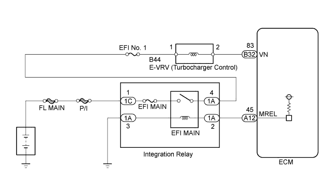
DTC P0234 Turbocharger / Supercharger Overboost Condition |
DTC P0299 Turbocharger / Supercharger Underboost |
DTC P1251 Turbocharger / Supercharger Overboost Condition (Too High) |
| DTC Detection Drive Pattern | DTC Detection Condition | Trouble Area |
| After warming up the engine, the vehicle is driven at a constant vehicle speed at an engine speed of 2400 rpm or more for 2 minutes | Actual turbocharger pressure "MAP" deviates by 30 kPa (225 mmHg, 8.9 in.Hg) or higher from the simulated target pressure "Target Booster Pressure" for 100 seconds at an engine speed of 2400 to 4000 rpm. (1 trip detection logic) |
|
| DTC Detection Drive Pattern | DTC Detection Condition | Trouble Area |
| After warming up the engine, the vehicle is driven at a constant vehicle speed at an engine speed of 2400 rpm or more for 2 minutes | When any condition below is met (2 trip detection logic):
|
|
| DTC Detection Drive Pattern | DTC Detection Condition | Trouble Area |
| After warming up the engine, fully depress the accelerator pedal for 5 seconds or more so that the engine speed is 2400 rpm or more. | The turbocharger pressure is 300 kPa (2250 mmHg, 89 in.Hg) or more for 5 seconds or more at an engine speed of 2000 to 4000 rpm. (1 trip detection logic) |
|
| DTC No. | Data List |
| P0234 |
|
| P0299 | |
| P1251 |
| 1.READ OUTPUT DTC (RECORD STORED DTC AND FREEZE FRAME DATA) |
Connect the intelligent tester to the DLC3.
Turn the ignition switch to ON and turn the tester on.
Enter the following menus: Powertrain / Engine and ECT / DTC.
Record the stored DTC and Freeze Frame Data.
| NEXT | |
 |
| 2.CHECK ANY OTHER DTCS OUTPUT (IN ADDITION TO DTC P0234, P0299 AND/OR P1251) |
Connect the intelligent tester to the DLC3.
Turn the ignition switch to ON and turn the tester on.
Enter the following menus: Powertrain / Engine and ECT / DTC.
Read the DTCs.
| Result | Proceed to |
| P0234, P0299 and/or P1251 | A |
| P0234, P0299 and/or P1251 and other DTCs | B |
|
| ||||
| A | |
|
| 3.READ VALUE USING INTELLIGENT TESTER (MAP AND TARGET BOOSTER PRESSURE) |
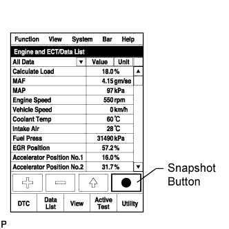 |
Connect the intelligent tester to the DLC3.
Start the engine and turn the tester on.
Enter the following menus: Powertrain / Engine and ECT / Data List / MAP and Target Booster Pressure.
Take a snapshot when the engine speed is maintained at 4500 rpm with no load.
Read the values of "MAP" and "Target Booster Pressure" in the Data List using the snapshot review function.
| Result | Proceed to |
| Difference between MAP and Target Booster Pressure is +/-15 kPa or higher | A |
| Except above | B |
|
| ||||
| A | |
|
| 4.CHECK AIR INTAKE SYSTEM |
Check for air leaks and blockages between the air cleaner case and turbocharger, and between turbocharger and intake manifold.
| Result | Proceed to |
| Leaks and/or blockages exist in the intake system | A |
| No leaks and/or blockages in the intake system | B |
|
| ||||
| A | |
|
| 5.REPAIR OR REPLACE AIR INTAKE SYSTEM |
| NEXT | |
|
| 6.READ VALUE USING INTELLIGENT TESTER (MAP AND TARGET BOOSTER PRESSURE) |
|
Connect the intelligent tester to the DLC3.
Start the engine and turn the tester on.
Enter the following menus: Powertrain / Engine and ECT / Data List / MAP and Target Booster Pressure.
Take a snapshot when the engine speed is maintained at 4500 rpm with no load.
Read the values of "MAP" and "Target Booster Pressure" in the Data List using the snapshot review function.
| Result | Proceed to |
| Difference between MAP and Target Booster Pressure is +/-15 kPa or higher | A |
| Except above | B |
|
| ||||
| A | |
|
| 7.CHECK CONNECTION OF VACUUM HOSE |
Check the turbocharger system vacuum hose connections
|
| ||||
| OK | |
|
| 8.INSPECT E-VRV FOR TURBOCHARGER CONTROL (E-VRV RESISTANCE) |
Inspect the E-VRV (Click here).
|
| ||||
| OK | |
|
| 9.CHECK TURBOCHARGER SUB-ASSEMBLY |
Check the turbocharger sub-assembly (Click here).
|
| ||||
| OK | |
|
| 10.CHECK HARNESS AND CONNECTOR (E-VRV FOR TURBOCHARGER CONTROL - ECM) |
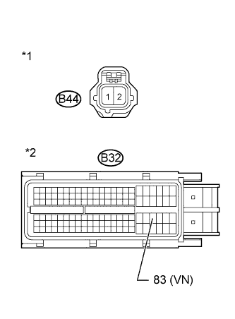 |
Disconnect the E-VRV connector.
Disconnect the ECM connector.
Measure the resistance according to the value(s) in the table below.
| Tester Connection | Condition | Specified Condition |
| B44-2 - B32-83 (VN) | Always | Below 1 Ω |
| Tester Connection | Condition | Specified Condition |
| B44-2 or B32-83 (VN) - Body ground | Always | 10 kΩ or higher |
| *1 | Front view of wire harness connector (to E-VRV) |
| *2 | Front view of wire harness connector (to ECM) |
Reconnect the E-VRV connector.
Reconnect the ECM connector.
|
| ||||
| OK | |
|
| 11.CHECK DIESEL THROTTLE BODY ASSEMBLY |
|
Connect the intelligent tester to the DLC3.
Start the engine and turn the tester on.
Enter the following menus: Powertrain / Engine and ECT / Data List / Actual Throttle Position.
Take a snapshot when accelerating with the accelerator fully depressed.
Read the value of "Actual Throttle Position" in the Data List using the snapshot review function.
|
| ||||
| OK | |
|
| 12.CHECK EGR VALVE ASSEMBLY |
|
Connect the intelligent tester to the DLC3.
Start the engine and turn the tester on.
Enter the following menus: Powertrain / Engine and ECT / Data List / Actual EGR Valve Pos..
Take a snapshot when accelerating with the accelerator fully depressed.
Read the value of "Actual EGR Valve Pos." in the Data List using the snapshot review function.
|
| ||||
| OK | |
|
| 13.READ VALUE USING INTELLIGENT TESTER (INJECTION FEEDBACK VAL #1 TO #4) |
Connect the intelligent tester to the DLC3.
Turn the ignition switch to ON and turn the tester on.
Start the engine and warm it up.
Enter the following menus: Powertrain / Engine and ECT / Data List / Injection Feedback Val #1 to #4.
Read the values.
| Item | Engine Speed* | Reference Value |
| Injection Feedback Val #1 to #4 | Idling | -3.0 to 3.0 mm3/st |
|
| ||||
| OK | |
|
| 14.CHECK ANY OTHER DTCS OUTPUT (IN ADDITION TO DTC P0234, P0299 AND/OR P1251) |
Connect the intelligent tester to the DLC3.
Clear the DTCs (Click here).
Turn the ignition switch off for 30 seconds or more.
Start the engine and warm it up for 1 minute or more.
Turn the tester on.
Read the value of Engine Speed from the Freeze Frame Data recorded previously.
After warming up the engine, drive the vehicle at a constant vehicle speed at an engine speed of 2400 rpm or more for 2 minutes.
With the engine warmed up, fully depress the accelerator pedal for 5 seconds or more so that the engine speed is 2400 rpm or more.
Enter the following menus: Powertrain / Engine and ECT / DTC / Pending.
Read the DTC.
| Result | Proceed to |
| No output | A |
| P0234, P0299 and/or P1251 | B |
|
| ||||
| A | ||
 | ||
| ||
| 15.REPLACE FUEL INJECTOR OF MALFUNCTIONING CYLINDER |
Replace the fuel injector (Click here).
| NEXT | |
|
| 16.BLEED AIR FROM FUEL SYSTEM |
Bleed the air from the fuel system .
| NEXT | |
|
| 17.REGISTER INJECTOR COMPENSATION CODE AND PERFORM PILOT QUANTITY LEARNING |
Register the injector compensation code .
Perform the fuel injector pilot quantity learning .
|
| ||||
| 18.REPAIR OR REPLACE VACUUM HOSE |
Repair or replace the vacuum hose.
|
| ||||
| 19.REPLACE E-VRV FOR TURBOCHARGER CONTROL |
Replace the E-VRV (Click here).
|
| ||||
| 20.REPLACE TURBOCHARGER SUB-ASSEMBLY |
Replace the turbocharger sub-assembly (Click here).
|
| ||||
| 21.REPAIR OR REPLACE HARNESS OR CONNECTOR |
Repair or replace the harness or connector.
|
| ||||
| 22.REPLACE DIESEL THROTTLE BODY ASSEMBLY |
Replace the diesel throttle body assembly (Click here).
|
| ||||
| 23.REPLACE EGR VALVE ASSEMBLY |
Replace the EGR valve assembly (Click here).
|
| ||||
| 24.REPLACE ECM |
Replace the ECM (Click here).
| NEXT | |
|
| 25.CONFIRM WHETHER MALFUNCTION HAS BEEN SUCCESSFULLY REPAIRED |
Connect the intelligent tester to the DLC3.
Clear the DTCs (Click here).
Turn the ignition switch off for 30 seconds or more.
Start the engine and warm it up.
Turn the tester on.
Read the value of Engine Speed from the Freeze Frame Data recorded previously.
After warming up the engine, drive the vehicle at a constant vehicle speed at an engine speed of 2400 rpm or more for 2 minutes.*A
With the engine warmed up, fully depress the accelerator pedal for 5 seconds or more so that the engine speed is 2400 rpm or more.*B
Confirm that the DTC is not output again.
Enter the following menus: Powertrain / Engine and ECT / Utility / All Readiness.
Input DTC P0234, P0299 and/or P1251.
Check that STATUS is NORMAL.
| NEXT | ||
| ||
| ||

