BRAKE CONTROL / DYNAMIC CONTROL SYSTEMS BRAKE ACTUATOR INSTALLATION
PROCEDURE

 44546A
1.INSTALL BRAKE ACTUATOR BOLT CUSHION
Install the 4 brake actuator bolt cushions to the brake actuator bracket assembly.
2.INSTALL BRAKE ACTUATOR CASE COLLAR
Install the 4 brake actuator case collars to the brake actuator bolt cushions.
- NOTICE:
-
Make sure the brake actuator case collars are in full contact with the brake actuator bolt cushions.
44590
3.INSTALL BRAKE ACTUATOR BRACKET ASSEMBLY
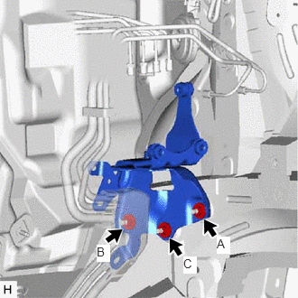
Install the brake actuator with bracket with the 3 nuts.
- Torque:
- 19 N*m (194 kgf*cm, 14 ft.*lbf)
- NOTICE:
- ·
Tighten the 3 nuts uniformly in alphabetical order.
·Be careful not to damage the brake tubes.
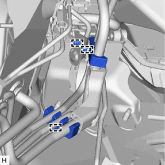
Connect the 3 clamps to the brake actuator bracket assembly.
4.INSTALL BRAKE ACTUATOR ASSEMBLY
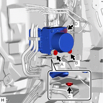
Install the brake actuator bracket assembly to the brake actuator assembly with the 4 bolts.
- Torque:
- 5.4 N*m (55 kgf*cm, 48 in.*lbf)
- NOTICE:
- ·
Tighten the 4 bolts uniformly in alphabetical order.
·A new brake actuator is filled with brake fluid. Therefore, make sure to connect the brake tube before removing the hole plug.
Connect the 3 clamps to the brake actuator bracket assembly.
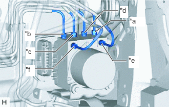
| *a | to Front Wheel Cylinder RH |
| *b | to Front Wheel Cylinder LH |
| *c | to Rear Wheel Cylinder RH |
| *d | to Rear Wheel Cylinder LH |
| *e | from Front Master Cylinder |
| *f | from Rear Master Cylinder |
Temporarily install each brake line to the correct positions of the brake actuator assembly with bracket as shown in the illustration.
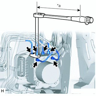
| *a | Torque Wrench Fulcrum Length |
Using a union nut wrench, tighten each 6 brake lines.
- Torque:
- Specified tightening torque : 15.2 N*m (155 kgf*cm, 11 ft.*lbf)
- HINT:
- ·
Calculate the torque wrench reading when changing the fulcrum length of the torque wrench.
Click hereGeneral>INTRODUCTION>REPAIR INSTRUCTION>PRECAUTION
·When using a union nut wrench (fulcrum length of 22 mm (0.8661 in.)) + torque wrench (fulcrum length of 162 mm (6.3779 in.)): 13.4 N*m (137 kgf*cm, 10 ft.*lbf)
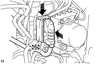
Connect the clamp to the brake actuator bracket assembly.
Connect the connector to the brake actuator assembly and lock the lock lever.
- NOTICE:
- ·
Before connecting the wire harness connector, make sure that the surfaces of the wire harness connector are free of foreign matter.
·After connecting the wire harness connector, make sure that the lock lever is securely locked.
33823
5.INSTALL NO. 1 TRANSMISSION CONTROL CABLE BRACKET (for Automatic Transmission)
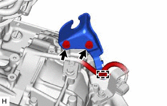
Attach the clamp.
Install the No. 1 transmission control cable bracket to the automatic transaxle assembly with the 2 bolts.
- Torque:
- 12 N*m (122 kgf*cm, 9 ft.*lbf)
6.CONNECT TRANSMISSION CONTROL CABLE ASSEMBLY (for Automatic Transmission)
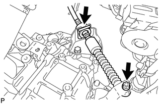
Connect the transmission control cable assembly to the No. 1 transmission control cable bracket with a new clip.
Connect the transmission control cable assembly to the transmission control shaft lever with the nut.
- Torque:
- 12 N*m (122 kgf*cm, 9 ft.*lbf)
82121
7.CONNECT ENGINE WIRE
except 2WW:
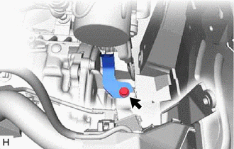
Install the wire harness clamp bracket with the bolt.
- Torque:
- 7.7 N*m (79 kgf*cm, 68 in.*lbf)
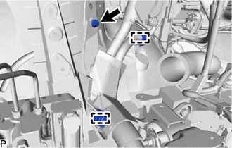
Connect the engine wire to the body with the bolt.
- Torque:
- 8.4 N*m (86 kgf*cm, 74 in.*lbf)
Attach the 2 clamps.
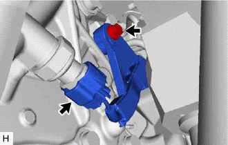
for CVT
Connect the connector.
Connect the engine wire with the bolt.
- Torque:
- 7.7 N*m (79 kgf*cm, 68 in.*lbf)
17119A
8.INSTALL AIR CLEANER BRACKET
for 2AD-FHV:
Click hereEngine / Hybrid System>2AD-FHV ENGINE MECHANICAL>ENGINE ASSEMBLY>INSTALLATION
for 2AD-FTV:
Click hereEngine / Hybrid System>2AD-FTV ENGINE MECHANICAL>ENGINE ASSEMBLY>INSTALLATION
23921
9.INSTALL FUEL FILTER SUPPORT (for 2WW)
10.INSTALL FUEL FILTER ASSEMBLY
for 2AD-FHV:
Click hereEngine / Hybrid System>2AD-FHV ENGINE MECHANICAL>ENGINE ASSEMBLY>INSTALLATION
for 2AD-FTV:
Click hereEngine / Hybrid System>2AD-FTV ENGINE MECHANICAL>ENGINE ASSEMBLY>INSTALLATION
for 2WW:
Click hereEngine / Hybrid System>2WW FUEL>FUEL FILTER>REPLACEMENT
17769
11.INSTALL AIR CLEANER SUPPORT
for 2AD-FHV:
Click hereEngine / Hybrid System>2AD-FHV ENGINE MECHANICAL>ENGINE ASSEMBLY>INSTALLATION
for 2AD-FTV:
Click hereEngine / Hybrid System>2AD-FTV ENGINE MECHANICAL>ENGINE ASSEMBLY>INSTALLATION
55789D
12.INSTALL NO. 3 COWL TOP PANEL INSULATOR (for 2WW)
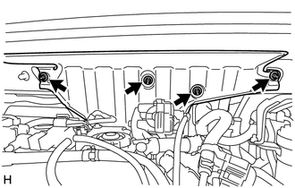
Install the No. 3 cowl top panel insulator with the 4 nuts.
- Torque:
- 5.5 N*m (56 kgf*cm, 49 in.*lbf)
13.INSTALL AIR CLEANER CASE SUB-ASSEMBLY
for 2AD-FHV:
Click hereEngine / Hybrid System>2AD-FHV ENGINE CONTROL>ECM>INSTALLATION
for 2AD-FTV:
Click hereEngine / Hybrid System>2AD-FTV ENGINE CONTROL>ECM>INSTALLATION
for 2AR-FE:
Click hereEngine / Hybrid System>2AR-FE ENGINE CONTROL>ECM>INSTALLATION
for 3ZR-FAE:
Click hereEngine / Hybrid System>3ZR-FAE ENGINE CONTROL>ECM>INSTALLATION
for 3ZR-FE:
Click hereEngine / Hybrid System>3ZR-FE ENGINE CONTROL>ECM>INSTALLATION
for 2WW:
Click hereEngine / Hybrid System>2WW ENGINE CONTROL>ECM>INSTALLATION
51444
14.INSTALL REAR ENGINE UNDER COVER LH
for 2AD-FHV:
Click hereEngine / Hybrid System>2AD-FHV ENGINE MECHANICAL>ENGINE ASSEMBLY>INSTALLATION
for 2AD-FTV:
Click hereEngine / Hybrid System>2AD-FTV ENGINE MECHANICAL>ENGINE ASSEMBLY>INSTALLATION
for 2AR-FE:
Click hereEngine / Hybrid System>2AR-FE ENGINE MECHANICAL>ENGINE ASSEMBLY>INSTALLATION
for 3ZR-FAE:
Click hereEngine / Hybrid System>3ZR-FE ENGINE MECHANICAL>ENGINE ASSEMBLY>INSTALLATION
for 3ZR-FE:
Click hereEngine / Hybrid System>3ZR-FE ENGINE MECHANICAL>ENGINE ASSEMBLY>INSTALLATION
for 2WW:
Click hereEngine / Hybrid System>2WW ENGINE MECHANICAL>ENGINE ASSEMBLY>INSTALLATION
15.CONNECT CABLE TO NEGATIVE BATTERY TERMINAL
- NOTICE:
-
When disconnecting the cable, some systems need to be initialized after the cable is reconnected (Click hereGeneral>INTRODUCTION>REPAIR INSTRUCTION>INITIALIZATION).
16.BLEED BRAKE SYSTEM
44510
17.INSPECT BRAKE ACTUATOR WITH GTS