METER / GAUGE / DISPLAY METER / GAUGE SYSTEM Speed Signal Circuit
DESCRIPTION
The vehicle speed signal consists of pulses sent to the combination meter assembly from the brake actuator assembly (skid control ECU).
WIRING DIAGRAM
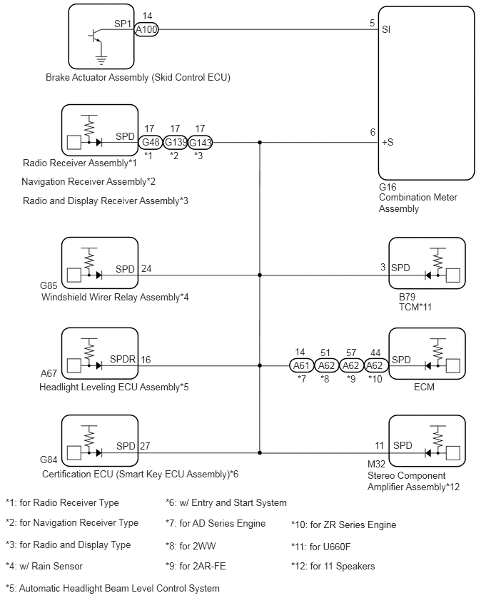
CAUTION / NOTICE / HINT
- NOTICE:
- ·
Before replacing the certification ECU (smart key ECU assembly), refer to the Service Bulletin.
·When replacing the combination meter assembly, make sure to replace it with a new one.
PROCEDURE
Check vehicle type.
- Result:
Proceed to for Radio and Display Type for Navigation Receiver Type for Radio Receiver Type
for Radio and Display Type
for Navigation Receiver Type
for Radio Receiver Type
*1: w/ Rain Sensor
*2: w/ Automatic Headlight Beam Level Control System
*3: w/ Entry and Start System
*4: for U660F
*5: for AD Series Engine
*6: except AD Series Engine
*7: for 11 Speakers
Disconnect the G16 combination meter assembly connector.
Disconnect the G85 windshield wiper relay assembly connector.*1
Disconnect the A67 headlight leveling ECU assembly connector.*2
Disconnect the G84 certification ECU (smart key ECU assembly) connector.*3
Disconnect the B79 TCM connector.*4
Disconnect the A61*5 or A62*6 ECM connector.
Disconnect the M32 stereo component amplifier assembly connector.*7
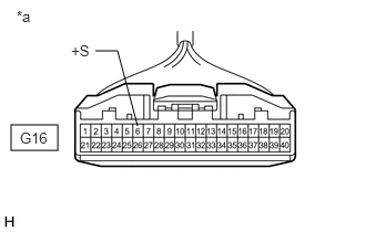
| *a | Front view of wire harness connector
(to Combination Meter Assembly) |
Measure the voltage according to the value(s) in the table below.
- Standard Voltage:
Tester Connection Switch Condition Specified Condition G16-6 (+S) - Body ground Ignition switch ON 4.5 to 14 V
- Result:
Proceed to OK NG
OK
NG
- NOTICE:
-
For vehicle except 11 speakers, proceed to next step.
*1: for Radio and Display Type
*2: for Navigation Receiver Type
*3: w/ Rain Sensor
*4: w/ Automatic Headlight Beam Level Control System
*5: w/ Entry and Start System
*6: for U660F
*7: for AD Series Engine
*8: except AD Series Engine
Disconnect the G16 combination meter assembly connector.
Disconnect the G143 radio and display receiver assembly connector.*1
Disconnect the G139 navigation receiver assembly connector.*2
Disconnect the G85 windshield wiper relay assembly connector.*3
Disconnect the A67 headlight leveling ECU assembly connector.*4
Disconnect the G84 certification ECU (smart key ECU assembly) connector.*5
Disconnect the B79 TCM connector.*6
Disconnect the A61*7 or A62*8 ECM connector.
| *a | Front view of wire harness connector
(to Combination Meter Assembly) |
Measure the voltage according to the value(s) in the table below.
- Standard Voltage:
Tester Connection Switch Condition Specified Condition G16-6 (+S) - Body ground Ignition switch ON 4.5 to 14 V
- Result:
Proceed to OK NG
OK
NG
- NOTICE:
-
For vehicle without a rain sensor, proceed to next step.
*1: for Radio Receiver Type
*2: for Navigation Receiver Type
*3: for Radio and Display Type
*4: w/ Automatic Headlight Beam Level Control System
*5: w/ Entry and Start System
*6: for U660F
*7: for AD Series Engine
*8: except AD Series Engine
Disconnect the G16 combination meter assembly connector.
Disconnect the G48 radio receiver assembly connector.*1
Disconnect the G139 navigation receiver assembly connector.*2
Disconnect the G143 radio and display receiver assembly connector.*3
Disconnect the A67 headlight leveling ECU assembly connector.*4
Disconnect the G84 certification ECU (smart key ECU assembly) connector.*5
Disconnect the B79 TCM connector.*6
Disconnect the A61*7 or A62*8 ECM connector.
| *a | Front view of wire harness connector
(to Combination Meter Assembly) |
Measure the voltage according to the value(s) in the table below.
- Standard Voltage:
Tester Connection Switch Condition Specified Condition G16-6 (+S) - Body ground Ignition switch ON 4.5 to 14 V
- Result:
Proceed to OK NG
OK
NG
- NOTICE:
-
For vehicle without an automatic headlight beam level control system, proceed to next step.
*1: for Radio Receiver Type
*2: for Navigation Receiver Type
*3: for Radio and Display Type
*4: w/ Rain Sensor
*5: w/ Entry and Start System
*6: for U660F
*7: for AD Series Engine
*8: except AD Series Engine
Disconnect the G16 combination meter assembly connector.
Disconnect the G48 radio receiver assembly connector.*1
Disconnect the G139 navigation receiver assembly connector.*2
Disconnect the G143 radio and display receiver assembly connector.*3
Disconnect the G85 windshield wiper relay assembly connector.*4
Disconnect the G84 certification ECU (smart key ECU assembly) connector.*5
Disconnect the B79 TCM connector.*6
Disconnect the A61*7 or A62*8 ECM connector.
| *a | Front view of wire harness connector
(to Combination Meter Assembly) |
Measure the voltage according to the value(s) in the table below.
- Standard Voltage:
Tester Connection Switch Condition Specified Condition G16-6 (+S) - Body ground Ignition switch ON 4.5 to 14 V
- Result:
Proceed to OK NG
OK
NG
- NOTICE:
-
For vehicle without an entry and start system, proceed to next step.
*1: for Radio Receiver Type
*2: for Navigation Receiver Type
*3: for Radio and Display Type
*4: w/ Rain Sensor
*5: w/ Automatic Headlight Beam Level Control System
*6: for U660F
*7: for AD Series Engine
*8: except AD Series Engine
Disconnect the G16 combination meter assembly connector.
Disconnect the G48 radio receiver assembly connector.*1
Disconnect the G139 navigation receiver assembly connector.*2
Disconnect the G143 radio and display receiver assembly connector.*3
Disconnect the G85 windshield wiper relay assembly connector.*4
Disconnect the A67 headlight leveling ECU assembly connector.*5
Disconnect the B79 TCM connector.*6
Disconnect the A61*7 or A62*8 ECM connector.
| *a | Front view of wire harness connector
(to Combination Meter Assembly) |
Measure the voltage according to the value(s) in the table below.
- Standard Voltage:
Tester Connection Switch Condition Specified Condition G16-6 (+S) - Body ground Ignition switch ON 4.5 to 14 V
- Result:
Proceed to OK NG
OK
NG
- NOTICE:
-
For vehicle except U660F, proceed to next step.
*1: for Radio Receiver Type
*2: for Navigation Receiver Type
*3: for Radio and Display Type
*4: w/ Rain Sensor
*5: w/ Automatic Headlight Beam Level Control System
*6: w/ Entry and Start System
*7: for AD Series Engine
*8: except AD Series Engine
Disconnect the G16 combination meter assembly connector.
Disconnect the G48 radio receiver assembly connector.*1
Disconnect the G139 navigation receiver assembly connector.*2
Disconnect the G143 radio and display receiver assembly connector.*3
Disconnect the G85 windshield wiper relay assembly connector.*4
Disconnect the A67 headlight leveling ECU assembly connector.*5
Disconnect the G84 certification ECU (smart key ECU assembly) connector.*6
Disconnect the A61*7 or A62*8 ECM connector.
| *a | Front view of wire harness connector
(to Combination Meter Assembly) |
Measure the voltage according to the value(s) in the table below.
- Standard Voltage:
Tester Connection Switch Condition Specified Condition G16-6 (+S) - Body ground Ignition switch ON 4.5 to 14 V
- Result:
Proceed to OK NG
OK
NG
*1: for Radio Receiver Type
*2: for Navigation Receiver Type
*3: for Radio and Display Type
*4: w/ Rain Sensor
*5: w/ Automatic Headlight Beam Level Control System
*6: w/ Entry and Start System
*7: for U660F
Disconnect the G16 combination meter assembly connector.
Disconnect the G48 radio receiver assembly connector.*1
Disconnect the G139 navigation receiver assembly connector.*2
Disconnect the G143 radio and display receiver assembly connector.*3
Disconnect the G85 windshield wiper relay assembly connector.*4
Disconnect the A67 headlight leveling ECU assembly connector.*5
Disconnect the G84 certification ECU (smart key ECU assembly) connector.*6
Disconnect the B79 TCM connector.*7
| *a | Front view of wire harness connector
(to Combination Meter Assembly) |
Measure the voltage according to the value(s) in the table below.
- Standard Voltage:
Tester Connection Switch Condition Specified Condition G16-6 (+S) - Body ground Ignition switch ON 4.5 to 14 V
- Result:
Proceed to OK NG
OK
NG
Disconnect the A100 brake actuator assembly (skid control ECU) connector.
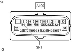
| *a | Front view of wire harness connector
(to Skid Control ECU [Brake Actuator Assembly]) |
Measure the voltage according to the value(s) in the table below.
- Standard Voltage:
Tester Connection Switch Condition Specified Condition A100-14 (SP1) - Body ground Ignition switch ON 11 to 14 V
- Result:
Proceed to OK NG
OK
NG
Remove the combination meter assembly with the connector(s) still connected.
Click hereVehicle Interior>METER / GAUGE / DISPLAY>COMBINATION METER>REMOVAL
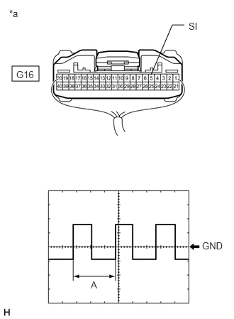
| *a | Component with harness connected
(Combination Meter Assembly) |
Connect an oscilloscope to terminal G16-5 (SI) and body ground.
Check the signal waveform according to the condition(s) in the table below.
| Item | Condition |
|---|---|
| Tester Connection | G16-5 (SI) - Body ground |
| Tool Setting | 5 V/DIV., 20 ms./DIV. |
| Vehicle Condition | Driving at approximately 20 km/h (12 mph) |
- HINT:
-
When the system is functioning normally, one wheel revolution generates 4 pulses. As the vehicle speed increases, the width indicated by A in the illustration narrows.
- OK:
The waveform displayed is as shown in the illustration.
- Result:
Proceed to OK NG
OK
NG
*1: w/ Rain Sensor
*2: w/ Automatic Headlight Beam Level Control System
*3: w/ Entry and Start System
*4: for U660F
*5: for AD Series Engine
*6: except AD Series Engine
Disconnect the G16 combination meter assembly connector.
Disconnect the G85 windshield wiper relay assembly connector.*1
Disconnect the A67 headlight leveling ECU assembly connector.*2
Disconnect the G84 certification ECU (smart key ECU assembly) connector.*3
Disconnect the B79 TCM connector.*4
Disconnect the A61*5 or A62*6 ECM connector.
| *a | Front view of wire harness connector
(to Combination Meter Assembly) |
Measure the voltage according to the value(s) in the table below.
- Standard Voltage:
Tester Connection Switch Condition Specified Condition G16-6 (+S) - Body ground Ignition switch ON 4.5 to 14 V
- Result:
Proceed to OK NG
OK
NG
*1: w/ Rain Sensor
*2: w/ Automatic Headlight Beam Level Control System
*3: w/ Entry and Start System
*4: for U660F
*5: for AD Series Engine
*6: except AD Series Engine
*7: for 11 Speakers
Disconnect the G16 combination meter assembly connector.
Disconnect the G143 radio and display receiver assembly connector.
Disconnect the G85 windshield wiper relay assembly connector.*1
Disconnect the A67 headlight leveling ECU assembly connector.*2
Disconnect the G84 certification ECU (smart key ECU assembly) connector.*3
Disconnect the B79 TCM connector.*4
Disconnect the A61*5 or A62*6 ECM connector.
Disconnect the M32 stereo component amplifier assembly connector.*7
Measure the resistance according to the value(s) in the table below.
- Standard Resistance:
Tester Connection Condition Specified Condition G16-6 (+S) - G143-17 (SPD) Always Below 1 Ω G16-6 (+S) or G143-17 (SPD) - Body ground Always 10 kΩ or higher
- Result:
Proceed to OK NG
OK
NG
*1: for Radio and Display Type
*2: for Navigation Receiver Type
*3: w/ Rain Sensor
*4: w/ Automatic Headlight Beam Level Control System
*5: w/ Entry and Start System
*6: for U660F
*7: for AD Series Engine
*8: except AD Series Engine
Disconnect the G16 combination meter assembly connector.
Disconnect the M32 stereo component amplifier assembly connector.
Disconnect the G143 radio and display receiver assembly connector.*1
Disconnect the G139 navigation receiver assembly connector.*2
Disconnect the G85 windshield wiper relay assembly connector.*3
Disconnect the A67 headlight leveling ECU assembly connector.*4
Disconnect the G84 certification ECU (smart key ECU assembly) connector.*5
Disconnect the B79 TCM connector.*6
Disconnect the A61*7 or A62*8 ECM connector.
Measure the resistance according to the value(s) in the table below.
- Standard Resistance:
Tester Connection Condition Specified Condition G16-6 (+S) - M32-11 (SPD) Always Below 1 Ω G16-6 (+S) or M32-11 (SPD) - Body ground Always 10 kΩ or higher
- Result:
Proceed to OK NG
OK
NG
*1: for Radio Receiver Type
*2: for Navigation Receiver Type
*3: for Radio and Display Type
*4: w/ Automatic Headlight Beam Level Control System
*5: w/ Entry and Start System
*6: for U660F
*7: for AD Series Engine
*8: except AD Series Engine
Disconnect the G16 combination meter assembly connector.
Disconnect the G85 windshield wiper relay assembly connector.
Disconnect the G48 radio receiver assembly connector.*1
Disconnect the G139 navigation receiver assembly connector.*2
Disconnect the G143 radio and display receiver assembly connector.*3
Disconnect the A67 headlight leveling ECU assembly connector.*4
Disconnect the G84 certification ECU (smart key ECU assembly) connector.*5
Disconnect the B79 TCM connector.*6
Disconnect the A61*7 or A62*8 ECM connector.
Measure the resistance according to the value(s) in the table below.
- Standard Resistance:
Tester Connection Condition Specified Condition G16-6 (+S) - G85-24 (SPD) Always Below 1 Ω G16-6 (+S) or G85-24 (SPD) - Body ground Always 10 kΩ or higher
- Result:
Proceed to OK NG
OK
NG
*1: for Radio Receiver Type
*2: for Navigation Receiver Type
*3: for Radio and Display Type
*4: w/ Rain Sensor
*5: w/ Entry and Start System
*6: for U660F
*7: for AD Series Engine
*8: except AD Series Engine
Disconnect the G16 combination meter assembly connector.
Disconnect the A67 headlight leveling ECU assembly connector.
Disconnect the G48 radio receiver assembly connector.*1
Disconnect the G139 navigation receiver assembly connector.*2
Disconnect the G143 radio and display receiver assembly connector.*3
Disconnect the G85 windshield wiper relay assembly connector.*4
Disconnect the G84 certification ECU (smart key ECU assembly) connector.*5
Disconnect the B79 TCM connector.*6
Disconnect the A61*7 or A62*8 ECM connector.
Measure the resistance according to the value(s) in the table below.
- Standard Resistance:
Tester Connection Condition Specified Condition G16-6 (+S) - A67-16 (SPDR) Always Below 1 Ω G16-6 (+S) or A67-16 (SPDR) - Body ground Always 10 kΩ or higher
- Result:
Proceed to OK NG
OK
NG
*1: for Radio Receiver Type
*2: for Navigation Receiver Type
*3: for Radio and Display Type
*4: w/ Rain Sensor
*5: w/ Automatic Headlight Beam Level Control System
*6: for U660F
*7: for AD Series Engine
*8: except AD Series Engine
Disconnect the G16 combination meter assembly connector.
Disconnect the G84 certification ECU (smart key ECU assembly) connector.
Disconnect the G48 radio receiver assembly connector.*1
Disconnect the G139 navigation receiver assembly connector.*2
Disconnect the G143 radio and display receiver assembly connector.*3
Disconnect the G85 windshield wiper relay assembly connector.*4
Disconnect the A67 headlight leveling ECU assembly connector.*5
Disconnect the B79 TCM connector.*6
Disconnect the A61*7 or A62*8 ECM connector.
Measure the resistance according to the value(s) in the table below.
- Standard Resistance:
Tester Connection Condition Specified Condition G16-6 (+S) - A67-16 (SPDR) Always Below 1 Ω G16-6 (+S) or A67-16 (SPDR) - Body ground Always 10 kΩ or higher
- Result:
Proceed to OK NG
OK
NG
*1: for Radio Receiver Type
*2: for Navigation Receiver Type
*3: for Radio and Display Type
*4: w/ Rain Sensor
*5: w/ Automatic Headlight Beam Level Control System
*6: w/ Entry and Start System
*7: for AD Series Engine
*8: except AD Series Engine
Disconnect the G16 combination meter assembly connector.
Disconnect the B79 TCM connector.
Disconnect the G48 radio receiver assembly connector.*1
Disconnect the G139 navigation receiver assembly connector.*2
Disconnect the G143 radio and display receiver assembly connector.*3
Disconnect the G85 windshield wiper relay assembly connector.*4
Disconnect the A67 headlight leveling ECU assembly connector.*5
Disconnect the G84 certification ECU (smart key ECU assembly) connector.*6
Disconnect the A61*7 or A62*8 ECM connector.
Measure the resistance according to the value(s) in the table below.
- Standard Resistance:
Tester Connection Condition Specified Condition G16-6 (+S) - B79-3 (SPD) Always Below 1 Ω G16-6 (+S) or B79-3 (SPD) - Body ground Always 10 kΩ or higher
- Result:
Proceed to OK NG
OK
NG
*1: for AD Series Engine
*2: except AD Series Engine
*3: for Radio Receiver Type
*4: for Navigation Receiver Type
*5: for Radio and Display Type
*6: w/ Rain Sensor
*7: w/ Automatic Headlight Beam Level Control System
*8: w/ Entry and Start System
*9: for U660F
Disconnect the G16 combination meter assembly connector.
Disconnect the A61*1 or A62*2 ECM connector.
Disconnect the G48 radio receiver assembly connector.*3
Disconnect the G139 navigation receiver assembly connector.*4
Disconnect the G143 radio and display receiver assembly connector.*5
Disconnect the G85 windshield wiper relay assembly connector.*6
Disconnect the A67 headlight leveling ECU assembly connector.*7
Disconnect the G84 certification ECU (smart key ECU assembly) connector.*8
Disconnect the B79 TCM connector.*9
Measure the resistance according to the value(s) in the table below.
- Standard Resistance:
for AD Series Engine Tester Connection Condition Specified Condition G16-6 (+S) - A61-14 (SPD) Always Below 1 Ω G16-6 (+S) or A61-14 (SPD) - Body ground Always 10 kΩ or higher
2AR-FE Tester Connection Condition Specified Condition G16-6 (+S) - A62-57 (SPD) Always Below 1 Ω G16-6 (+S) or A62-57 (SPD) - Body ground Always 10 kΩ or higher
3ZR-FE, 3ZR-FAE Tester Connection Condition Specified Condition G16-6 (+S) - A62-44 (SPD) Always Below 1 Ω G16-6 (+S) or A62-44 (SPD) - Body ground Always 10 kΩ or higher
2WW Tester Connection Condition Specified Condition G16-6 (+S) - A62-57 (SPD) Always Below 1 Ω G16-6 (+S) or A62-57 (SPD) - Body ground Always 10 kΩ or higher
- Result:
Proceed to OK NG
OK
for 2AD-FHV: Click hereEngine / Hybrid System>2AD-FHV ENGINE CONTROL>ECM>REMOVAL
for 2AD-FTV: Click hereEngine / Hybrid System>2AD-FTV ENGINE CONTROL>ECM>REMOVAL
for 2AR-FE: Click hereEngine / Hybrid System>2AR-FE ENGINE CONTROL>ECM>REMOVAL
for 2WW: Click hereEngine / Hybrid System>2WW ENGINE CONTROL>ECM>REMOVAL
for 3ZR-FAE: Click hereEngine / Hybrid System>3ZR-FAE ENGINE CONTROL>ECM>REMOVAL
for 3ZR-FE: Click hereEngine / Hybrid System>3ZR-FE ENGINE CONTROL>ECM>REMOVAL
NG
Disconnect the G16 combination meter assembly connector.
Disconnect the A100 brake actuator assembly (skid control ECU) connector.
Measure the resistance according to the value(s) in the table below.
- Standard Resistance:
Tester Connection Condition Specified Condition G16-5 (SI) - A100-14 (SP1) Always Below 1 Ω G16-5 (SI) or A100-14 (SP1) - Body ground Always 10 kΩ or higher
- Result:
Proceed to OK NG
OK
NG
*1: w/ Rain Sensor
*2: w/ Automatic Headlight Beam Level Control System
*3: w/ Entry and Start System
*4: for U660F
*5: for AD Series Engine
*6: except AD Series Engine
Disconnect the G16 combination meter assembly connector.
Disconnect the G139 navigation receiver assembly connector.
Disconnect the G85 windshield wiper relay assembly connector.*1
Disconnect the A67 headlight leveling ECU assembly connector.*2
Disconnect the G84 certification ECU (smart key ECU assembly) connector.*3
Disconnect the B79 TCM connector.*4
Disconnect the A61*5 or A62*6 ECM connector.
Measure the resistance according to the value(s) in the table below.
- Standard Resistance:
Tester Connection Condition Specified Condition G16-6 (+S) - G139-17 (SPD) Always Below 1 Ω G16-6 (+S) or G139-17 (SPD) - Body ground Always 10 kΩ or higher
- Result:
Proceed to OK NG
OK
NG
*1: w/ Rain Sensor
*2: w/ Automatic Headlight Beam Level Control System
*3: w/ Entry and Start System
*4: for U660F
*5: for AD Series Engine
*6: except AD Series Engine
Disconnect the G16 combination meter assembly connector.
Disconnect the G85 windshield wiper relay assembly connector.*1
Disconnect the A67 headlight leveling ECU assembly connector.*2
Disconnect the G84 certification ECU (smart key ECU assembly) connector.*3
Disconnect the B79 TCM connector.*4
Disconnect the A61*5 or A62*6 ECM connector.
| *a | Front view of wire harness connector
(to Combination Meter Assembly) |
Measure the voltage according to the value(s) in the table below.
- Standard Voltage:
Tester Connection Switch Condition Specified Condition G16-6 (+S) - Body ground Ignition switch ON 4.5 to 14 V
- Result:
Proceed to OK NG
OK
NG
*1: w/ Rain Sensor
*2: w/ Automatic Headlight Beam Level Control System
*3: w/ Entry and Start System
*4: for U660F
*5: for AD Series Engine
*6: except AD Series Engine
Disconnect the G16 combination meter assembly connector.
Disconnect the G48 radio receiver assembly connector.
Disconnect the G85 windshield wiper relay assembly connector.*1
Disconnect the A67 headlight leveling ECU assembly connector.*2
Disconnect the G84 certification ECU (smart key ECU assembly) connector.*3
Disconnect the B79 TCM connector.*4
Disconnect the A61*5 or A62*6 ECM connector.
Measure the resistance according to the value(s) in the table below.
- Standard Resistance:
Tester Connection Condition Specified Condition G16-6 (+S) - G48-17 (SPD) Always Below 1 Ω G16-6 (+S) or G48-17 (SPD) - Body ground Always 10 kΩ or higher
- Result:
Proceed to OK NG
OK
NG