HEATING / AIR CONDITIONING AIR CONDITIONING UNIT(for A25B-FXS) INSTALLATION
CAUTION / NOTICE / HINT
- HINT:
-
A bolt without a torque specification is shown in the standard bolt chart.
-
Click hereGeneral>SPECIFICATIONS>STANDARD BOLT>SPECIFIED TORQUE FOR STANDARD BOLTS
PROCEDURE

 88539G
1.INSTALL COOLER UNIT DRAIN HOSE GROMMET
87201
2.INSTALL NO. 1 AIR DUCT SUB-ASSEMBLY
3.INSTALL AIR CONDITIONING UNIT ASSEMBLY
4.CONNECT INSTRUMENT PANEL WIRE
Attach the clamp.
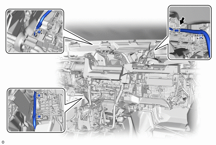
Connect the connector.
88650N
5.INSTALL AIR CONDITIONING AMPLIFIER ASSEMBLY
6.INSTALL INSTRUMENT PANEL REINFORCEMENT ASSEMBLY WITH AIR CONDITIONING UNIT ASSEMBLY
87128
7.INSTALL HEATER GROMMET
88539J
8.CONNECT DRAIN COOLER HOSE
55307C
9.TEMPORARILY INSTALL NO. 2 INSTRUMENT PANEL BRACE SUB-ASSEMBLY
55306A
10.TEMPORARILY INSTALL NO. 1 INSTRUMENT PANEL BRACE SUB-ASSEMBLY
11.TIGHTEN INSTRUMENT PANEL REINFORCEMENT ASSEMBLY WITH AIR CONDITIONING UNIT ASSEMBLY
Tighten the 3 bolts, 2 nuts (A), and 2 screws in the order shown in the illustration.
- HINT:
-
5 and 6 can be done in either order.
- Torque:
- Bolt : 9.8 N*m (100 kgf*cm, 87 in.*lbf)
- Nut (A) : 18 N*m (184 kgf*cm, 13 ft.*lbf)
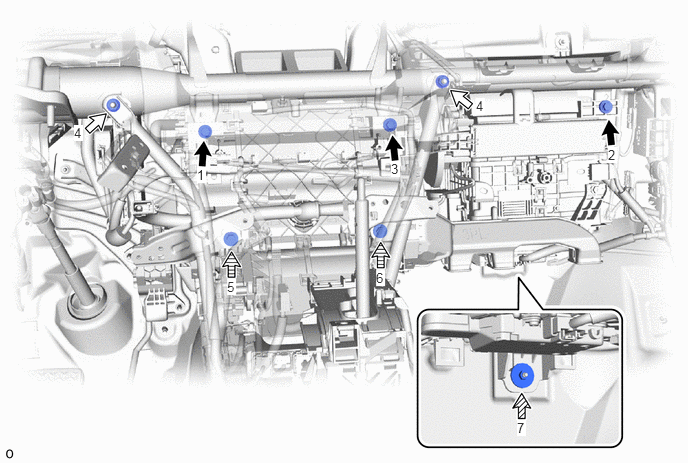

|
Bolt | 
|
Nut (A) |

|
Nut (B) | 
|
Screw |
Tighten the nut (B).
- Torque:
- 9.8 N*m (100 kgf*cm, 87 in.*lbf)
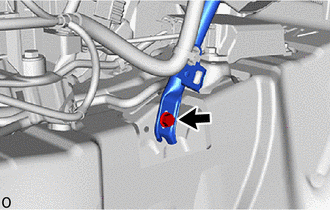
Tighten the No. 2 instrument panel brace sub-assembly with the bolt.
- Torque:
- 20 N*m (204 kgf*cm, 15 ft.*lbf)
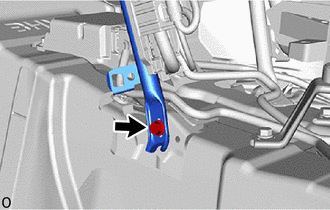
Tighten the No. 1 instrument panel brace sub-assembly with the bolt.
- Torque:
- 20 N*m (204 kgf*cm, 15 ft.*lbf)
12.CONNECT INSTRUMENT PANEL WIRE
Attach the clamp.
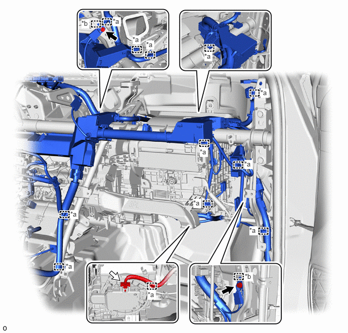
| *a | Clamp | *b | Guide |
|
|
Bolt |
|
Connector |
Connect the connector.
Attach the guide.
Connect the 2 ground wires with the 2 bolts.
- Torque:
- 8.5 N*m (87 kgf*cm, 75 in.*lbf)
82877
13.INSTALL ECU INTEGRATION BOX RH
14.CONNECT INSTRUMENT PANEL WIRE
Connect the lever connector.
Click hereVehicle Interior>SUPPLEMENTAL RESTRAINT SYSTEMS>CENTER AIRBAG SENSOR ASSEMBLY>INSTALLATION
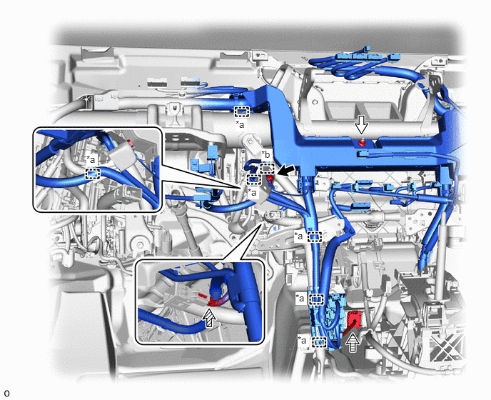
| *a | Clamp | *b | Guide |
|
|
Bolt |
|
Nut |
|
|
Connector |
|
Lever Connector |
Attach the clamp.
Connect the connector.
Attach the guide.
Connect the ground wire with the bolt.
- Torque:
- 8.5 N*m (87 kgf*cm, 75 in.*lbf)
Install the nut.
- Torque:
- 8.0 N*m (82 kgf*cm, 71 in.*lbf)
Attach the clamp.
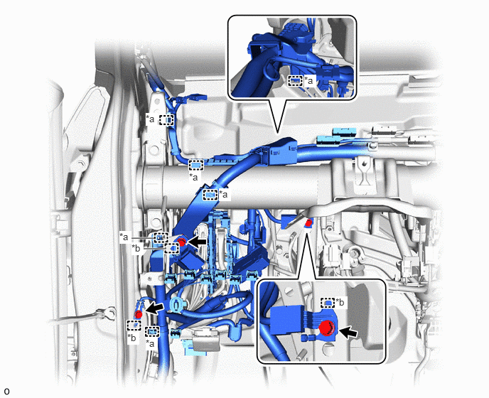
| *a | Clamp | *b | Guide |
Attach the guide.
Connect the 3 ground wires with the 3 bolts.
- Torque:
- 8.5 N*m (87 kgf*cm, 75 in.*lbf)
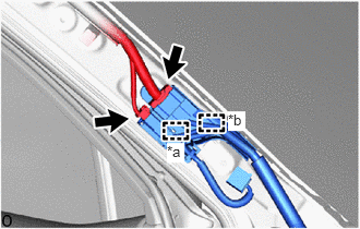
| *a | Clamp |
| *b | Guide |
Connect the 2 connectors.
Attach the guide and clamp.
15.INSTALL INSTRUMENT PANEL JUNCTION BLOCK ASSEMBLY WITH MAIN BODY ECU
55308B
16.INSTALL NO. 3 INSTRUMENT PANEL TO COWL BRACE SUB-ASSEMBLY
55085
17.INSTALL NO. 2 HEATER TO REGISTER DUCT SUB-ASSEMBLY
58861B
18.INSTALL NO. 1 CONSOLE BOX DUCT
87212G
19.INSTALL REAR NO. 3 AIR DUCT
87212H
20.INSTALL REAR NO. 4 AIR DUCT
87212
21.INSTALL REAR NO. 1 AIR DUCT
- HINT:
-
Use the same procedure described as for the rear No. 3 air duct.
87212F
22.INSTALL REAR NO. 2 AIR DUCT
- HINT:
-
Use the same procedure described as for the rear No. 4 air duct.
55215D
23.INSTALL NO. 3 DASH PANEL INSULATOR PAD
58510C
24.INSTALL FRONT FLOOR FRONT CARPET ASSEMBLY
Install the front floor front carpet assembly to its original position as shown in the illustration.
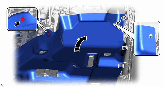

|
Return to Original Position | - | - |
Attach the guide.
Install the clip.
Install the front floor front carpet assembly to its original position as shown in the illustration.
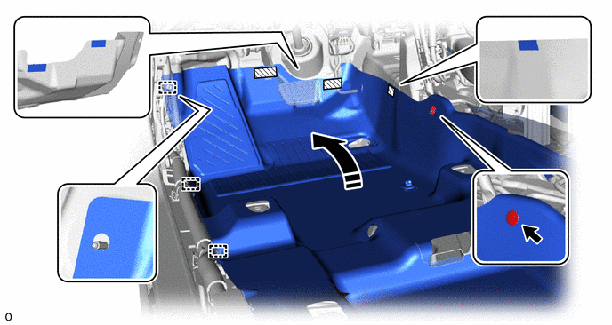
|
|
Return to Original Position | 
|
Fastener |
Attach the guide.
Attach each fastener.
Install the clip.
58569D
25.INSTALL FRONT FLOOR CAUTION PLATE COVER
78010F
26.INSTALL ACCELERATOR PEDAL ASSEMBLY
78118
27.INSTALL ACCELERATOR PEDAL PAD
62414A
28.INSTALL LOWER CENTER PILLAR GARNISH LH
Install the lower center pillar garnish LH.
Click hereVehicle Interior>INTERIOR PANELS / TRIM>ROOF HEADLINING>INSTALLATION
Return the front door opening trim weatherstrip LH to its original position.
Click hereVehicle Exterior>DOOR / HATCH>FRONT DOOR OPENING TRIM WEATHERSTRIP>INSTALLATION
Return the rear door opening trim weatherstrip LH to its original position.
Click hereVehicle Exterior>DOOR / HATCH>REAR DOOR OPENING TRIM WEATHERSTRIP>INSTALLATION
73220
29.INSTALL FRONT SEAT OUTER BELT ASSEMBLY LH
67918E
30.INSTALL REAR DOOR SCUFF PLATE LH
62413A
31.INSTALL LOWER CENTER PILLAR GARNISH RH
- HINT:
-
Use the same procedure described as for the lower center pillar garnish LH.
73210
32.INSTALL FRONT SEAT OUTER BELT ASSEMBLY RH
- HINT:
-
Use the same procedure described as for the front seat outer belt assembly LH.
67917C
33.INSTALL REAR DOOR SCUFF PLATE RH
- HINT:
-
Use the same procedure described as for the rear door scuff plate LH.
73233
34.INSTALL OUTER LAP BELT ANCHOR COVER
35.INSTALL NAVIGATION ECU WITH BRACKET (w/ Dummy Case)
- HINT:
-
Use the same procedure described as for the navigation ECU with bracket.
-
Click hereAudio / Visual / Telematics>NAVIGATION / MULTI INFO DISPLAY>NAVIGATION ECU>INSTALLATION
45250
36.INSTALL STEERING COLUMN ASSEMBLY
37.INSTALL INSTRUMENT PANEL SAFETY PAD ASSEMBLY
38.INSTALL FRONT SEAT ASSEMBLY LH
for Manual Seat:
Click hereVehicle Interior>SEAT>FRONT SEAT ASSEMBLY (for Manual Seat)>INSTALLATION
for Power Seat:
Click hereVehicle Interior>SEAT>FRONT SEAT ASSEMBLY (for Power Seat)>INSTALLATION
39.INSTALL FRONT SEAT ASSEMBLY RH
- HINT:
-
Use the same procedure as for the LH side.
87245
40.CONNECT INLET HEATER WATER HOSE
87246
41.CONNECT OUTLET HEATER WATER HOSE
88710E
42.CONNECT AIR CONDITIONING TUBE AND ACCESSORY ASSEMBLY
88707
43.CONNECT SUCTION PIPE SUB-ASSEMBLY
44.INSTALL HOLE PLUG
55704B
45.INSTALL COWL VENTILATOR PANEL SUB-ASSEMBLY
Install the cowl ventilator panel sub-assembly with the 4 bolts and 4 nuts.
- Torque:
- Bolt : 5.5 N*m (56 kgf*cm, 49 in.*lbf)
- Nut : 21 N*m (214 kgf*cm, 15 ft.*lbf)
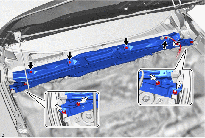
|
|
Bolt |
|
Nut |
Attach the clamp.
55752
46.INSTALL COWL VENTILATOR SPLASH SHIELD
- HINT:
-
Install using the same procedure that is performed when replacement of the cowl ventilator splash shield is necessary.
-
Click hereVehicle Exterior>WIPER / WASHER>FRONT WIPER MOTOR>INSTALLATION
47.INSTALL WINDSHIELD WIPER MOTOR AND LINK ASSEMBLY
48.ADD ENGINE COOLANT (for Engine)
49.INSPECT FOR COOLANT LEAK (for Engine)
50.CHARGE AIR CONDITIONING SYSTEM WITH REFRIGERANT
51.WARM UP COMPRESSOR
52.INSPECT FOR REFRIGERANT LEAK