HEATING / AIR CONDITIONING AIR CONDITIONING UNIT(for A25A-FXS) INSTALLATION
CAUTION / NOTICE / HINT
- HINT:
- ·
Use the same procedure as for the LHD and RHD vehicles.
·The procedure listed below is for the LHD vehicles.
·A bolt without a torque specification is shown in the standard bolt chart.
Click hereGeneral>SPECIFICATIONS>STANDARD BOLT>SPECIFIED TORQUE FOR STANDARD BOLTS
PROCEDURE

 88539G
1.INSTALL COOLER UNIT DRAIN HOSE GROMMET
- NOTICE:
- Perform this procedure only when removal/installation of the cooler unit drain hose grommet is necessary.
-
After removing the cooler unit drain hose grommet, replace it with a new one to prevent water from entering.
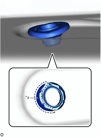
| *a | Lip Penetrate Area |
Attach one side of the lip on a new cooler unit drain hose grommet (approximately 1/3 of the circumference) to the body hole (fit it to the hole).
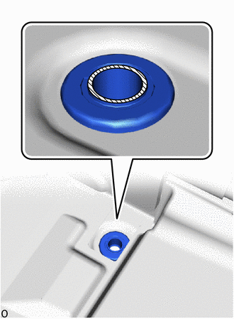

|
Rib Upper Surface |
Press the entire upper surface of the rib on the cooler unit drain hose grommet, and fit the entire circumference of the lip to the hole.
- NOTICE:
- ·
If the lip on the cooler unit drain hose grommet is not completely fit to the hole, water or noise may enter the interior. When fitting the lip to the hole, make sure that there are no gaps between the lip and body.
·Do not allow any foreign matter to be trapped between the cooler unit drain hose grommet and installation area, as this may allow noise to enter.
·Removing the cooler unit drain hose grommet after it has been installed damages the lip due to burrs on the body punch hole (vehicle exterior). This may reduce contact between the edge of the lip and body and cause water to enter the interior. Therefore, do not reuse the cooler unit drain hose grommet.
·When installing the cooler unit drain hose grommet, do not leave the lip only partially fit to the hole (as in the previous step). This may reduce contact due to lip deformation and cause water to enter the interior. Once you have started to install the part, complete the installation without stopping.
58511K
2.INSTALL NO. 1 FLOOR MAT (for RHD)
- HINT:
-
Perform this procedure only when removal/installation of the cooler unit drain hose grommet is necessary.
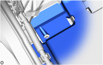
Return the No. 1 floor mat to its original state.
87201
3.INSTALL NO. 1 AIR DUCT SUB-ASSEMBLY
- HINT:
-
Perform this procedure only when removal/installation of the No. 1 air duct sub-assembly is necessary.
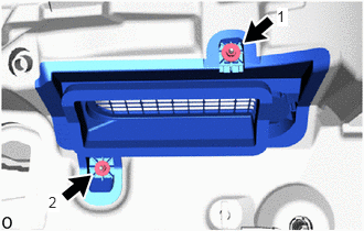
Install the air duct sub-assembly with the 2 nuts in the order shown in the illustration.
- Torque:
- 9.8 N*m (100 kgf*cm, 87 in.*lbf)
- NOTICE:
- ·
Make sure there are no cracks in the No. 1 air duct sub-assembly.
·Make sure no foreign matter, such as the dash panel insulator, is trapped between the cowl and seal packing.
·Make sure that the seal packing is securely attached to the cowl on the body. Look from the engine compartment and check that it does not drop down into the fresh air vent. (If foreign matter, such as the dash panel insulator, is trapped or if the seal packing is not securely attached, water or air from gaps may enter the interior.)
4.INSTALL AIR CONDITIONING UNIT ASSEMBLY
- NOTICE:
- ·
Be sure to support the air conditioning unit assembly when installing it because failure to do so may cause the bracket of the air conditioning unit assembly to break.
·When installing the air conditioning unit assembly, eliminate static electricity by touching the vehicle body to prevent the components from being damaged.
·Be careful not to damage the internal components of the instrument panel reinforcement assembly and air conditioning unit assembly on the glass etc. Only perform installation after first taking the appropriate actions.
·Do not allow the air conditioning unit assembly to strike the airbag sensor assembly. Doing so may damage the heater case, causing water leaks.
Temporarily set the air conditioning unit assembly nearby the position where it is to be installed.
- NOTICE:
- When carrying the air conditioning unit assembly, hold the bottom of the assembly. Do not hold the following parts.
- ·
Do not hold the air conditioning harness assembly. Otherwise, static electricity from the technician may damage the air conditioning harness assembly.
·Do not hold the heater core or pipe of the heater radiator unit sub-assembly. Otherwise, the pipe may detach, the clamp may be damaged, or the crimped areas of the heater core and pipe of the heater radiator unit sub-assembly may be damaged, causing coolant to leak.
·Do not hold the air conditioning radiator damper servo sub-assembly, blower damper servo sub-assembly or link. Otherwise, the servo motor may become misaligned, causing abnormal operation noise, temperature control defects, or air leaks due to sealing defects in the doors.
·Do not hold the door. Doing so may cause air leaks due to closing defects resulting from excessive opening/closing. Also, keep the door free from oil and grease.
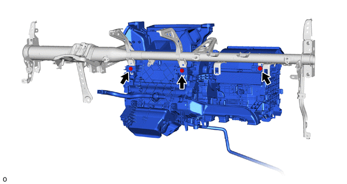
Temporarily install the air conditioning unit assembly to the instrument panel reinforcement assembly with the 3 bolts.
5.CONNECT INSTRUMENT PANEL WIRE
for LHD:
Attach the clamp.
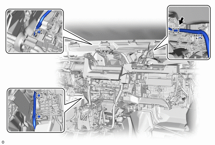
Connect the connector.
for RHD:
Attach the clamp.
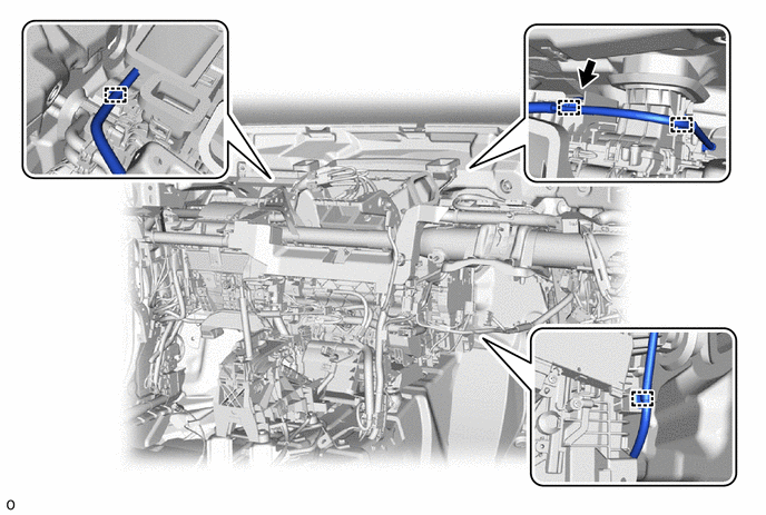
Connect the connector.
88650N
6.INSTALL AIR CONDITIONING AMPLIFIER ASSEMBLY
7.INSTALL INSTRUMENT PANEL REINFORCEMENT ASSEMBLY WITH AIR CONDITIONING UNIT ASSEMBLY
- NOTICE:
- ·
Be sure to support the air conditioning unit assembly when installing it because failure to do so may cause the bracket of the air conditioning unit assembly to break.
·When installing the air conditioning unit assembly, eliminate static electricity by touching the vehicle body to prevent the components from being damaged.
·Be careful not to damage the internal components of the instrument panel reinforcement assembly with air conditioning unit assembly on the glass etc. Only perform installation after first taking the appropriate actions.
Install the instrument panel reinforcement assembly with air conditioning unit assembly to the guide as shown in the illustration.
- NOTICE:
- When carrying the instrument panel reinforcement assembly with air conditioning unit assembly, hold the bottom of the assembly. Do not hold the following parts.
- ·
Do not hold the air conditioning harness assembly. Otherwise, static electricity from the technician may damage the air conditioning harness assembly.
·Do not hold the heater core or pipe of the heater radiator unit sub-assembly. Otherwise, the pipe may detach, the clamp may be damaged, or the crimped areas of the heater core and pipe of the heater radiator unit sub-assembly may be damaged, causing coolant to leak.
·Do not hold the air conditioning radiator damper servo sub-assembly, blower damper servo sub-assembly or link. Otherwise, the servo motor may become misaligned, causing abnormal operation noise, temperature control defects, or air leaks due to sealing defects in the doors.
·Do not hold the door. Doing so may cause air leaks due to closing defects resulting from excessive opening/closing. Also, keep the door free from oil and grease.
- NOTICE:
- ·
Do not allow the heater radiator unit sub-assembly heater pipe or cooler expansion valve to strike the body.
·Make sure that both parts are securely installed to the guide.
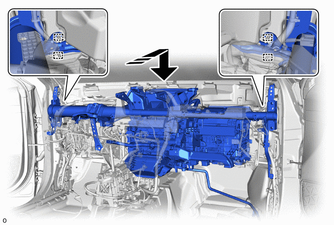

|
Install in this Direction | - | - |
Temporarily install the 4 bolts (C).
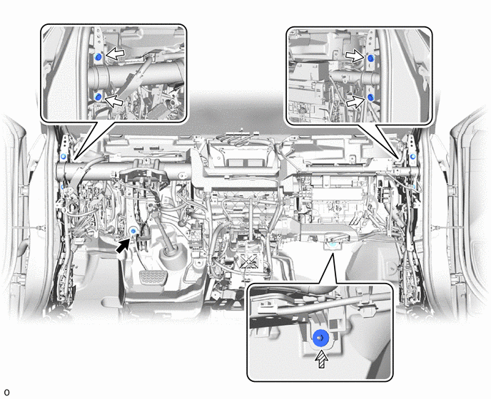

|
Bolt (B) | 
|
Bolt (C) |

|
Nut | - | - |
Temporarily install the bolt (B).
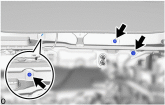
|
|
Bolt (A) |
Temporarily install the 3 bolts (A).
Temporarily install the nut.
Tighten the 4 bolts (C).
- Torque:
- 25 N*m (255 kgf*cm, 18 ft.*lbf)
Tighten the 3 bolts (A).
- Torque:
- 25 N*m (255 kgf*cm, 18 ft.*lbf)
Tighten the bolt (B).
- Torque:
- 15 N*m (153 kgf*cm, 11 ft.*lbf)
87128
8.INSTALL HEATER GROMMET
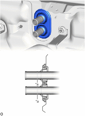
| *a | Spool |
Install the heater grommet.
- NOTICE:
- ·
Push the heater grommet lip seal until it passes over the spools of the heater pipes as shown in the illustration.
·Make sure that the lip portion of the heater grommet does not sit on top of the spools of the heater pipes.
·Make sure that there is no gap between the heater grommet and dash panel.
·Securely fit the heater grommet onto the dash panel. Otherwise, water may enter from the engine room or cause increased noise, vibration or harshness.
88539J
9.CONNECT DRAIN COOLER HOSE
- NOTICE:
-
If the cooler unit drain hose grommet was removed from the body, replace it with a new one.
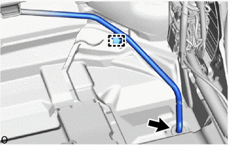
Connect the drain cooler hose to the cooler unit drain hose grommet.
- NOTICE:
-
When installing the drain cooler hose, make sure it is not twisted or crushed. Otherwise, water may leak into the interior.
Attach the clamp.
55307C
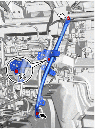
10.TEMPORARILY INSTALL NO. 2 INSTRUMENT PANEL BRACE SUB-ASSEMBLY
|
|
Bolt |
|
|
Nut |
|
|
Screw |
Temporarily install the No. 2 instrument panel brace sub-assembly with the bolt, nut and screw.
55306A
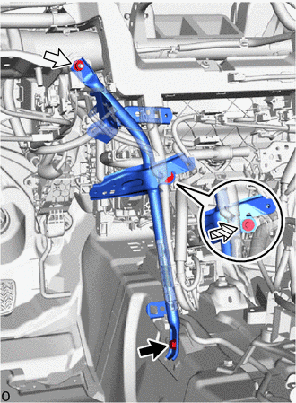
11.TEMPORARILY INSTALL NO. 1 INSTRUMENT PANEL BRACE SUB-ASSEMBLY
|
|
Bolt |
|
|
Nut |
|
|
Screw |
Temporarily install the No. 1 instrument panel brace sub-assembly with the bolt, nut and screw.
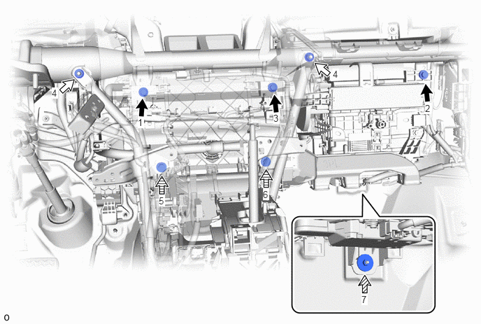
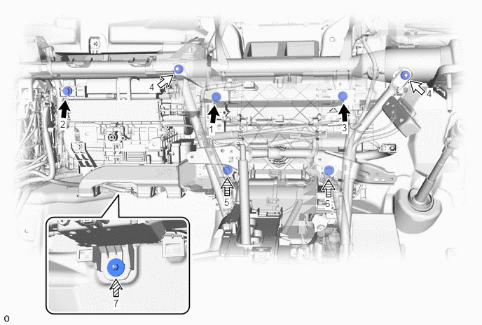
12.TIGHTEN INSTRUMENT PANEL REINFORCEMENT ASSEMBLY WITH AIR CONDITIONING UNIT ASSEMBLY
for LHD:
Tighten the 3 bolts, 2 nuts (A), and 2 screws in the order shown in the illustration.
- Torque:
- Bolt : 9.8 N*m (100 kgf*cm, 87 in.*lbf)
- Nut (A) : 18 N*m (184 kgf*cm, 13 ft.*lbf)
- HINT:
-
5 and 6 can be done in either order.
|
|
Bolt |
|
Nut (A) |
|
|
Nut (B) | 
|
Screw |
Tighten the nut (B).
- Torque:
- 9.8 N*m (100 kgf*cm, 87 in.*lbf)
for RHD:
Tighten the 3 bolts, 2 nuts (A), and 2 screws in the order shown in the illustration.
- Torque:
- Bolt : 9.8 N*m (100 kgf*cm, 87 in.*lbf)
- Nut (A) : 18 N*m (184 kgf*cm, 13 ft.*lbf)
- HINT:
-
5 and 6 can be done in either order.
|
|
Bolt |
|
Nut (A) |
|
|
Nut (B) |
|
Screw |
Tighten the nut (B).
- Torque:
- 9.8 N*m (100 kgf*cm, 87 in.*lbf)
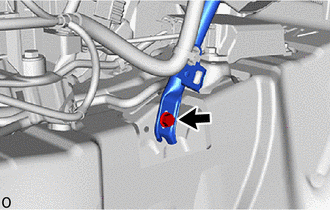
Tighten the No. 2 instrument panel brace sub-assembly with the bolt.
- Torque:
- 20 N*m (204 kgf*cm, 15 ft.*lbf)
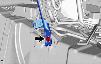
Tighten the No. 1 instrument panel brace sub-assembly with the bolt.
- Torque:
- 20 N*m (204 kgf*cm, 15 ft.*lbf)
13.CONNECT INSTRUMENT PANEL WIRE
for LHD:
Attach the clamp.
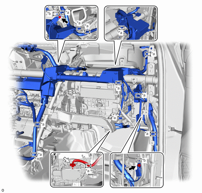
| *a | Clamp | *b | Guide |
|
|
Bolt |
|
Connector |
Connect the connector.
Attach the guide.
Connect the 2 ground wires with the 2 bolts.
- Torque:
- 8.5 N*m (87 kgf*cm, 75 in.*lbf)
for RHD:
Attach the clamp.
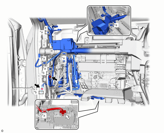
| *a | Clamp | *b | Guide |
|
|
Bolt |
|
Connector |
Connect the connector.
Attach the guide.
Connect the 2 ground wires with the 2 bolts.
- Torque:
- 8.5 N*m (87 kgf*cm, 75 in.*lbf)
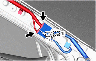
| *a | Clamp |
| *b | Guide |
Connect the 2 connectors.
Attach the guide and clamp.
14.INSTALL INSTRUMENT PANEL JUNCTION BLOCK ASSEMBLY WITH MAIN BODY ECU (for RHD)
89981
15.INSTALL HYBRID VEHICLE CONTROL ECU ASSEMBLY (for RHD)
82877
16.INSTALL ECU INTEGRATION BOX RH (for LHD)
17.CONNECT INSTRUMENT PANEL WIRE
for LHD:
Connect the lever connector.
Click hereVehicle Interior>SUPPLEMENTAL RESTRAINT SYSTEMS>CENTER AIRBAG SENSOR ASSEMBLY>INSTALLATION
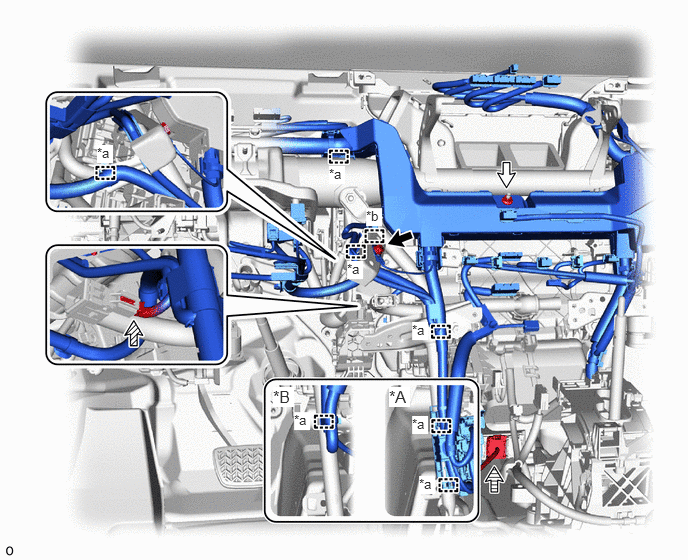
| *A | for Type A | *B | for Type B |
| *a | Clamp | *b | Guide |
|
|
Bolt |
|
Nut |
|
|
Connector |
|
Lever Connector |
Attach the clamp.
Connect the connector.
Attach the guide.
Connect the ground wire with the bolt.
- Torque:
- 8.5 N*m (87 kgf*cm, 75 in.*lbf)
Install the nut.
- Torque:
- 8.0 N*m (82 kgf*cm, 71 in.*lbf)
Attach the clamp.
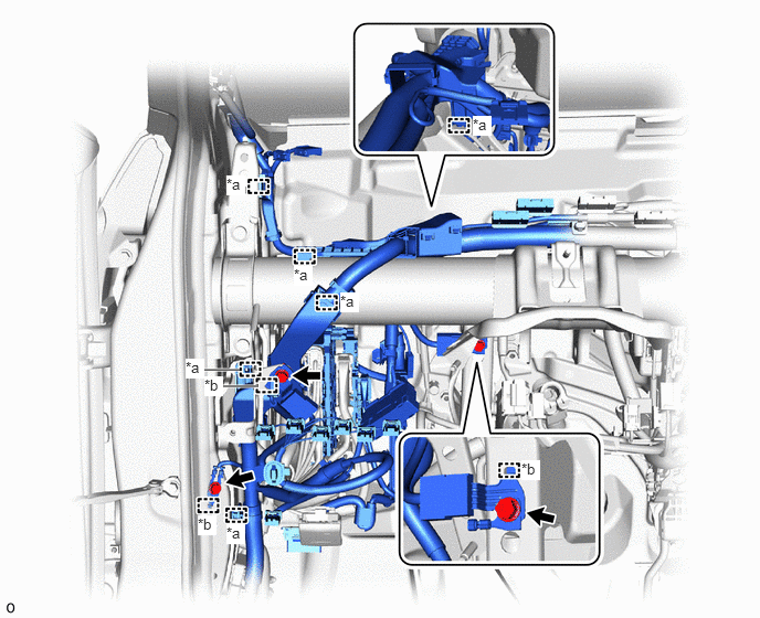
| *a | Clamp | *b | Guide |
Attach the guide.
Connect the 3 ground wires with the 3 bolts.
- Torque:
- 8.5 N*m (87 kgf*cm, 75 in.*lbf)
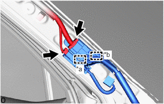
| *a | Clamp |
| *b | Guide |
Connect the 2 connectors.
Attach the guide and clamp.
for RHD:
Connect the lever connector.
Click hereVehicle Interior>SUPPLEMENTAL RESTRAINT SYSTEMS>CENTER AIRBAG SENSOR ASSEMBLY>INSTALLATION
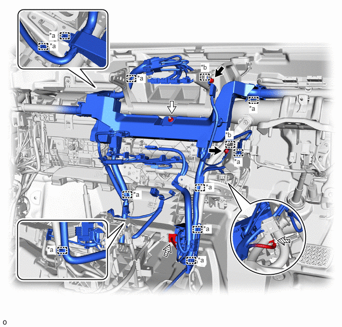
| *a | Clamp | *b | Guide |
|
|
Bolt |
|
Nut |
|
|
Connector |
|
Lever Connector |
Attach the clamp.
Connect the connector.
Attach the guide.
Connect the 2 ground wires with the 2 bolts.
- Torque:
- 8.5 N*m (87 kgf*cm, 75 in.*lbf)
Install the nut.
- Torque:
- 8.0 N*m (82 kgf*cm, 71 in.*lbf)
Attach the clamp.
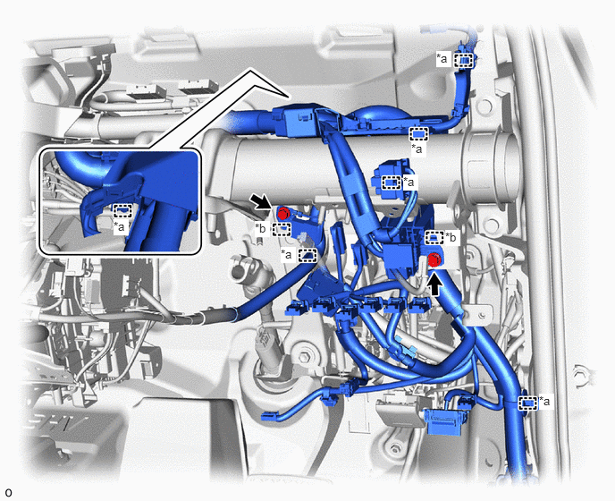
| *a | Clamp | *b | Guide |
Attach the guide.
Connect the 2 ground wires with the 2 bolts.
- Torque:
- 8.5 N*m (87 kgf*cm, 75 in.*lbf)
82877
18.INSTALL ECU INTEGRATION BOX RH (for RHD)
19.INSTALL INSTRUMENT PANEL JUNCTION BLOCK ASSEMBLY WITH MAIN BODY ECU (for LHD)
55308B
20.INSTALL NO. 3 INSTRUMENT PANEL TO COWL BRACE SUB-ASSEMBLY
for RHD:
Click herePower Source / Network>NETWORKING>NETWORK GATEWAY ECU (for RHD)>INSTALLATION
55085
21.INSTALL NO. 2 HEATER TO REGISTER DUCT SUB-ASSEMBLY
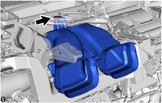
Install the No. 2 heater to register duct sub-assembly with the clip.
58861B
22.INSTALL NO. 1 CONSOLE BOX DUCT
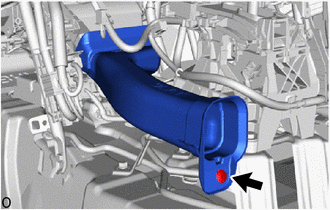
Install the No. 1 console box duct with the clip.
87212G
23.INSTALL REAR NO. 3 AIR DUCT
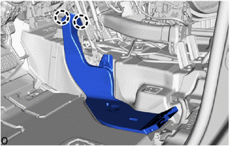
Attach the claw to install the rear No. 3 air duct.
87212H
24.INSTALL REAR NO. 4 AIR DUCT
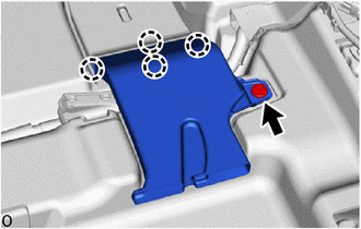
Attach the claw.
Install the rear No. 4 air duct with the clip.
87212
25.INSTALL REAR NO. 1 AIR DUCT
- HINT:
-
Use the same procedure described as for the rear No. 3 air duct.
87212F
26.INSTALL REAR NO. 2 AIR DUCT
- HINT:
-
Use the same procedure described as for the rear No. 4 air duct.
55215D
27.INSTALL NO. 3 DASH PANEL INSULATOR PAD
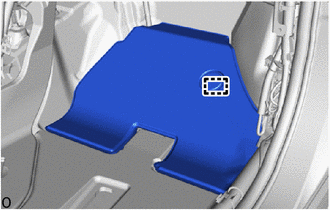
Attach the guide to install the No. 3 dash panel insulator pad.
58510C
28.INSTALL FRONT FLOOR FRONT CARPET ASSEMBLY
for LHD:
Install the front floor front carpet assembly to its original position as shown in the illustration.
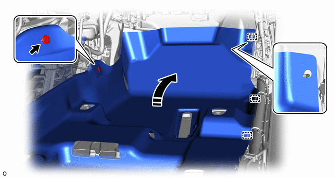
|
|
Return to Original Position | - | - |
Attach the guide.
Install the clip.
Install the front floor front carpet assembly to its original position as shown in the illustration.
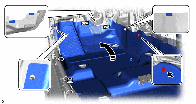
|
|
Return to Original Position |
|
Fastener |
Attach the guide.
Attach each fastener.
Install the clip.
for RHD:
Install the front floor front carpet assembly to its original position as shown in the illustration.
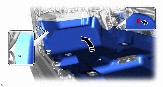
|
|
Return to Original Position | - | - |
Attach the guide.
Install the clip.
Install the front floor front carpet assembly to its original position as shown in the illustration.
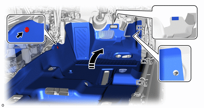
|
|
Return to Original Position |
|
Fastener |
Attach the guide.
Attach the fastener.
Install the clip.
58569D
29.INSTALL FRONT FLOOR CAUTION PLATE COVER
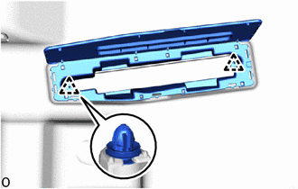
Attach the 2 clips to install the front floor caution plate cover.
While pressing at the positions shown in the illustration, attach the guide and claw.
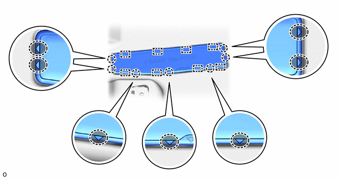

|
Press Position | - | - |
78010F
30.INSTALL ACCELERATOR PEDAL ASSEMBLY
78118
31.INSTALL ACCELERATOR PEDAL PAD
62414A
32.INSTALL LOWER CENTER PILLAR GARNISH LH
Install the lower center pillar garnish LH.
Click hereVehicle Interior>INTERIOR PANELS / TRIM>ROOF HEADLINING>INSTALLATION
Return the front door opening trim weatherstrip LH to its original position.
Click hereVehicle Exterior>DOOR / HATCH>FRONT DOOR OPENING TRIM WEATHERSTRIP>INSTALLATION
Return the rear door opening trim weatherstrip LH to its original position.
Click hereVehicle Exterior>DOOR / HATCH>REAR DOOR OPENING TRIM WEATHERSTRIP>INSTALLATION
73220
33.INSTALL FRONT SEAT OUTER BELT ASSEMBLY LH
67918E
34.INSTALL REAR DOOR SCUFF PLATE LH
62413A
35.INSTALL LOWER CENTER PILLAR GARNISH RH
- HINT:
-
Use the same procedure described as for the lower center pillar garnish LH.
73210
36.INSTALL FRONT SEAT OUTER BELT ASSEMBLY RH
- HINT:
-
Use the same procedure described as for the front seat outer belt assembly LH.
67917C
37.INSTALL REAR DOOR SCUFF PLATE RH
- HINT:
-
Use the same procedure described as for the rear door scuff plate LH.
73233
38.INSTALL OUTER LAP BELT ANCHOR COVER
39.INSTALL NAVIGATION ECU WITH BRACKET (w/ Navigation System)
40.INSTALL TELEPHONE TRANSCEIVER ASSEMBLY WITH BRACKET (w/ Telematics Transceiver)
for LHD:
Click hereAudio / Visual / Telematics>TELEMATICS>TELEMATICS TRANSCEIVER>INSTALLATION
for RHD:
Click hereAudio / Visual / Telematics>TELEMATICS>TELEMATICS TRANSCEIVER>INSTALLATION
41.INSTALL NAVIGATION ECU WITH BRACKET (w/ Dummy Case)
- HINT:
-
Use the same procedure described as for the navigation ECU with bracket or telephone transceiver assembly with bracket.
45250
42.INSTALL STEERING COLUMN ASSEMBLY
43.INSTALL INSTRUMENT PANEL SAFETY PAD ASSEMBLY
44.INSTALL FRONT SEAT ASSEMBLY LH
for Manual Seat:
Click hereVehicle Interior>SEAT>FRONT SEAT ASSEMBLY (for Manual Seat)>INSTALLATION
for Power Seat:
Click hereVehicle Interior>SEAT>FRONT SEAT ASSEMBLY (for Power Seat)>INSTALLATION
45.INSTALL FRONT SEAT ASSEMBLY RH
- HINT:
-
Use the same procedure as for the LH side.
87245
46.CONNECT INLET HEATER WATER HOSE
Connect the inlet heater water hose as shown in the illustration.
- NOTICE:
- ·
Do not apply excessive force to the inlet heater water hose.
·Make sure the inlet heater water hose is securely inserted to the stopper. However, If the end of the inlet heater water hose is cut diagonally, it is acceptable for the entire circumference of the tip to not contact the stopper.
·Connect the inlet heater water hose so that its marking faces the top of the vehicle.
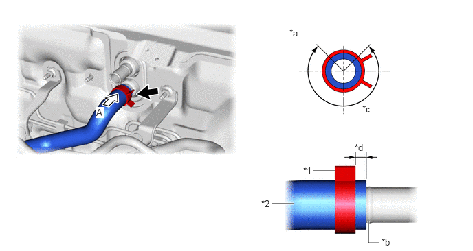
| *1 | Hose Clip | *2 | Inlet Heater Water Hose |
| *a | View A | *b | Stopper |
| *c | Hose Clip Installation Angle (270°) | *d | Hose Clip Installation Range (2 to 7 mm (0.0787 to 0.276 in.)) |
Make sure to install the hose clip within the range shown in the illustration.
87246
47.CONNECT OUTLET HEATER WATER HOSE
Connect the outlet heater water hose as shown in the illustration.
- NOTICE:
- ·
Do not apply excessive force to the outlet heater water hose.
·Make sure the outlet heater water hose is securely inserted to the stopper. However, If the end of the outlet heater water hose is cut diagonally, it is acceptable for the entire circumference of the tip to not contact the stopper.
·Connect the outlet heater water hose so that its marking faces the top of the vehicle.
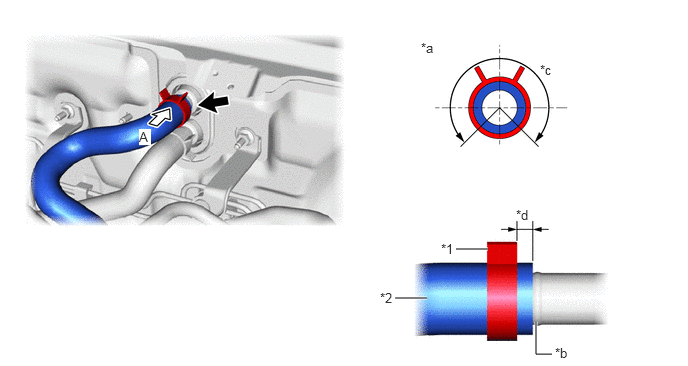
| *1 | Hose Clip | *2 | Outlet Heater Water Hose |
| *a | View A | *b | Stopper |
| *c | Hose Clip Installation Angle (270°) | *d | Hose Clip Installation Range (2 to 7 mm (0.0787 to 0.276 in.)) |
Make sure to install the hose clip within the range shown in the illustration.
- NOTICE:
-
Make sure that the hose clamps do not contact each other.
88710E
48.CONNECT AIR CONDITIONING TUBE AND ACCESSORY ASSEMBLY
Remove the vinyl tape wrapped around the connection of the air conditioning tube and accessory assembly and the air conditioning tube and accessory assembly.
Sufficiently apply compressor oil to a new O-ring and the fitting surface of the air conditioning tube and accessory assembly.
- Compressor Oil:
ND-OIL 11 or equivalent
- NOTICE:
-
Do not use any compressor oil other than ND-OIL 11 or equivalent. If any compressor oil other than ND-OIL 11 or equivalent is used, compressor motor insulation performance may decrease, resulting in leakage of electric power.
Install the O-ring to the air conditioning tube and accessory assembly.
- NOTICE:
-
Keep the O-ring and O-ring fitting surface free from foreign matter.
Connect the air conditioning tube and accessory assembly.
- NOTICE:
- ·
Do not apply excessive force to the air conditioning tube and accessory assembly.
·Make sure not to cut the O-ring while installing it. (Cut O-rings cannot be installed)
88707
49.CONNECT SUCTION PIPE SUB-ASSEMBLY
Remove the vinyl tape wrapped around the connection of the suction pipe sub-assembly and suction pipe sub-assembly.
Sufficiently apply compressor oil to a new O-ring and the fitting surface of the suction pipe sub-assembly.
- Compressor Oil:
ND-OIL 11 or equivalent
- NOTICE:
-
Do not use any compressor oil other than ND-OIL 11 or equivalent. If any compressor oil other than ND-OIL 11 or equivalent is used, compressor motor insulation performance may decrease, resulting in leakage of electric power.
Install the O-ring to the suction pipe sub-assembly.
- NOTICE:
-
Keep the O-ring and O-ring fitting surface free of foreign matter.
Connect the suction pipe sub-assembly.
- NOTICE:
- ·
Do not apply excessive force to the suction pipe sub-assembly.
·Make sure not to cut the O-ring while installing it. (Cut O-rings cannot be installed)
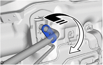
|
|
Rotate in this Direction |
Rotate the 1-point tightening plate as shown in the illustration.
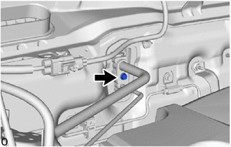
Insert the tube joint into the fitting hole securely and install the bolt.
- Torque:
- 9.8 N*m (100 kgf*cm, 87 in.*lbf)
50.INSTALL HOLE PLUG
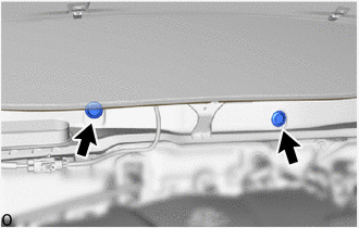
Install the 2 hole plugs.
55704B
51.INSTALL COWL VENTILATOR PANEL SUB-ASSEMBLY
Install the cowl ventilator panel sub-assembly with the 4 bolts and 4 nuts.
- Torque:
- Bolt : 5.5 N*m (56 kgf*cm, 49 in.*lbf)
- Nut : 21 N*m (214 kgf*cm, 15 ft.*lbf)
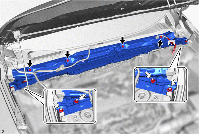
|
|
Bolt |
|
Nut |
Attach the clamp.
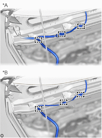
| *A | w/ Heated Windshield Defroster System |
| *B | w/ Windshield Deicer System |
Attach the clamp.
55752
52.INSTALL COWL VENTILATOR SPLASH SHIELD
- HINT:
-
Install using the same procedure that is performed when replacement of the cowl ventilator splash shield is necessary.
-
Click hereVehicle Exterior>WIPER / WASHER>FRONT WIPER MOTOR>INSTALLATION
53.INSTALL WINDSHIELD WIPER MOTOR AND LINK ASSEMBLY
54.ADD ENGINE COOLANT (for Engine)
55.INSPECT FOR COOLANT LEAK (for Engine)
56.CHARGE AIR CONDITIONING SYSTEM WITH REFRIGERANT
for HFC-134a (R134a):
Click hereVehicle Interior>HEATING / AIR CONDITIONING>REFRIGERANT (for HFC-134a(R134a))>REPLACEMENT
for HFO-1234yf (R1234yf):
Click hereVehicle Interior>HEATING / AIR CONDITIONING>REFRIGERANT (for HFO-1234yf(R1234yf))>REPLACEMENT
57.WARM UP COMPRESSOR
for HFC-134a (R134a):
Click hereVehicle Interior>HEATING / AIR CONDITIONING>REFRIGERANT (for HFC-134a(R134a))>REPLACEMENT
for HFO-1234yf (R1234yf):
Click hereVehicle Interior>HEATING / AIR CONDITIONING>REFRIGERANT (for HFO-1234yf(R1234yf))>REPLACEMENT
58.INSPECT FOR REFRIGERANT LEAK
for HFC-134a (R134a):
Click hereVehicle Interior>HEATING / AIR CONDITIONING>REFRIGERANT (for HFC-134a(R134a))>REPLACEMENT
for HFO-1234yf (R1234yf):
Click hereVehicle Interior>HEATING / AIR CONDITIONING>REFRIGERANT (for HFO-1234yf(R1234yf))>REPLACEMENT