8HP51 AUTOMATIC TRANSMISSION / TRANSAXLE B58 TRANSMISSION WIRE INSTALLATION
PROCEDURE

 82125
1.INSTALL TRANSMISSION WIRE
- NOTICE:
- ·
Improper routing of cables and wiring harnesses.
Trapped, crushed or damaged cables may cause short circuits and malfunctions.
-Route all cables without abrasions, do not trap and crush.
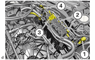
Connect and lock the connector (1).
Route the connector (2) to the integrated supply module.
Route the connector (3) to the ECM.
Secure the transmission wire at the bracket (4).
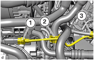
Connect and lock the connector (1) of the compressor with magnet clutch.
Secure clamps (2).
Secure clamp (3).
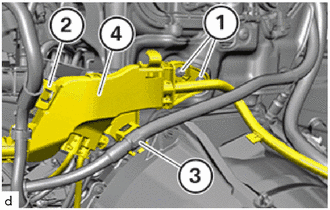
Mount cable channel (4).
Tighten the E8 bolts (1).
- Torque:
- 8.0 N*m (82 kgf*cm, 71 in.*lbf)
Lock clamp (2).
Secure positive battery cable at the clamp (3).
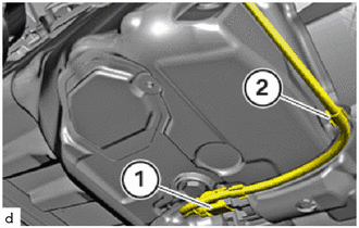
Connect and lock the connector (1) of the starter assembly.
Secure the cables (2) to the clamps .
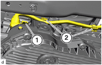
Connect and lock the connector (1) to the automatic transmission assembly.
Secure the cable with the clamps (2).
2.CONNECT All CONNECTORS FROM THE ECM AND FROM THE NO. 1 INTEGRATION RELAY
- HINT:
- ·
Follow instructions for removing and installing control units.
·For additional information see:
Click hereGeneral>INTRODUCTION>REPAIR INSTRUCTION>PRECAUTION
·Disconnecting control units may cause fault code entries and functional limitations. Fault code entries must be read out and deleted if necessary.
Connect all connectors and lock.
- HINT:
-
All connectors must engage audibly.
Connect all connectors and lock.
- HINT:
-
All connectors must engage audibly.
Install the cover.
- HINT:
-
The snap-lock couplings must engage audibly.
3.INSTALL PROPELLER SHAFT ASSEMBLY
57255
4.INSTALL REAR ENGINE MOUNTING MEMBER
58152C
5.INSTALL NO. 2 FLOOR HEAT INSULATOR
58151A
6.INSTALL NO. 1 FLOOR HEAT INSULATOR
- HINT:
-
Use the same as for the No. 2 floor heat insulator.
58151
7.INSTALL FRONT NO. 1 FLOOR HEAT INSULATOR
8.INSTALL EXHAUST PIPE ASSEMBLY
58166A
9.INSTALL FRONT FLOOR COVER LH
58165C
10.INSTALL FRONT FLOOR COVER RH
- HINT:
-
Use the same procedure as for the LH side.
51219
11.INSTALL FRONT SUSPENSION MEMBER LOWER PROTECTOR
12611
12.INSTALL NO. 1 ENGINE COVER
12601B
13.INSTALL NO. 1 ENGINE COVER SUB-ASSEMBLY
55788A
14.INSTALL COWL TOP VENTILATOR LOUVER PROTECTOR
85010
15.INSTALL FRONT WIPER MOTOR AND LINK ASSEMBLY
16.CONNECT CABLE TO NEGATIVE BATTERY TERMINAL