FRONT SUSPENSION FRONT SHOCK ABSORBER INSTALLATION
CAUTION / NOTICE / HINT
- HINT:
- ·
Use the same procedure for the RH side and LH side.
·The following procedure is for the LH side.
PROCEDURE

 48609
1.INSTALL FRONT SUSPENSION SUPPORT SUB-ASSEMBLY
- HINT:
-
Perform this procedure only when replacement of the front suspension support sub-assembly and front No. 1 shock absorber dust cover is necessary.
Check front No. 1 shock absorber dust cover and replace if necessary.
Slide front No. 1 shock absorber dust cover onto the front suspension support sub-assembly.
48158C
2.INSTALL FRONT LOWER COIL SPRING INSULATOR
Check front lower coil spring insulator and replace if necessary.
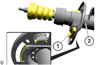
Mount front lower coil spring insulator (1) on the front shock absorber assembly (2).
- HINT:
-
Make sure the front lower coil spring insulator (1) is positioned correctly.
48331C
3.INSTALL FRONT SPRING BUMPER
Check front spring bumper and replace if necessary.
Mount the front spring bumper on the front shock absorber assembly.
4.INSTALL FRONT COIL SPRING
- NOTICE:
-
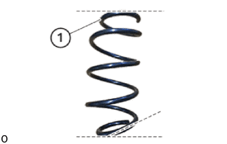
-
Flattened end (1) of the front coil spring lies on the front suspension support sub-assembly.
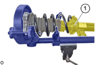
Feed front shock absorber (1) with front lower coil spring insulator and front spring bumper thread into the tensioned front coil spring and remove.
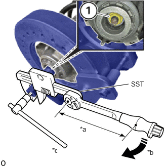
| *a | Torque Wrench Fulcrum Length |
| *b | Turn |
| *c | Hold |
Replace front support to front shock absorber nut (1).
Using SST, tighten front support to front shock absorber nut (1).
- SST
- 09700-WA250
09922-10010
- Torque:
- Specified tightening torque : 71 N*m (724 kgf*cm, 52 ft.*lbf)
- HINT:
- ·
Calculate the torque wrench reading when changing the fulcrum length of the torque wrench.
Click hereGeneral>INTRODUCTION>REPAIR INSTRUCTION>PRECAUTION
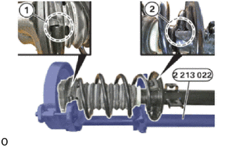
Upper front coil spring end (1) abuts against the front upper coil spring insulator.
Align front shock absorber with front lower coil spring insulator to lower front coil spring end (2).
Relax front coil spring tension with special tool 2 213 022 (31 3 340).
- SST
- 09700-WA190
Check position of lower front coil spring end (2), and correct if necessary.
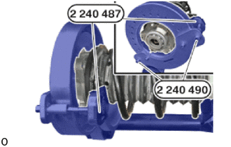
Loosen the screws 2 240 490.
- SST
- 09700-WA200
Remove the plate 2 240 487.
- SST
- 09700-WA200
Remove the front shock absorber with coil spring from the spring tensioner.
5.INSTALL FRONT SHOCK ABSORBER WITH COIL SPRING
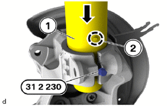
Spread the steering knuckle with the special tool 0 494 541 (31 2 230).
- SST
- 09600-WA030
Correctly align the positioning pin (2) on the front shock absorber with coil spring (1) with the steering knuckle and push it on up to the limit position in the direction of arrow.
Position the holder on the steering knuckle.
Replace the 18 mm bolt and 16 mm nut.
Insert the 18 mm bolt and tighten the 16 mm nut.
- Torque:
- 60 N*m (612 kgf*cm, 44 ft.*lbf)
Using SST, tighten the 16 mm nut an additional 180°.
- SST
- 09900-WA010
- HINT:
- ·
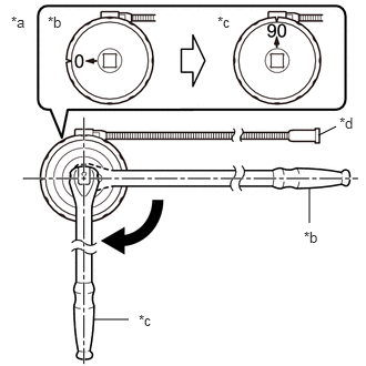 2.99,1.271 3.156,1.188 false 2.906,2.094 2.906,1.76 false 0.875,3 1.208,3 false 0.104,0.125 0.417,0.281 0.313,0.156 10 false *a 0.448,0.125 0.76,0.281 0.313,0.156 10 false *b 2.042,0.125 2.354,0.281 0.313,0.156 10 false *c 3.188,1.073 3.427,1.271 0.24,0.198 10 false *d 2.854,2.146 3.167,2.302 0.313,0.156 10 false *b 1.302,2.927 1.615,3.083 0.313,0.156 10 false *c
*a Example *b Before Tightening *c After Tightening *d Magnetic Portion
·The magnetic portion is used to secure the gauge to the vehicle.
·After first adjusting the needle of the gauge to 0°, tighten to the specified angle.
·Perform the work procedure carefully so that the gauge, etc. does not become tilted.
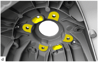
Clean the inner contact surfaces on the front shock absorber dome.
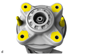
Clean the inner contact surface on the front suspension support sub-assembly.
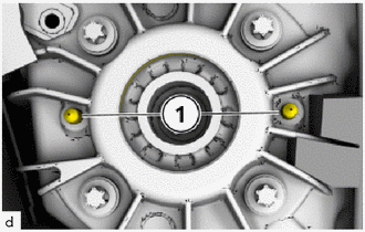
Correctly align the front shock absorber with coil spring including steering knuckle with the bore holes on the front shock absorber dome using the centering pins (1) and insert towards the top.
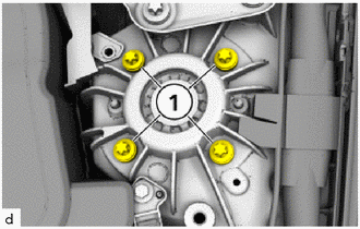
Replace the bolts (1).
Tighten the bolts (1).
- Torque:
- 28 N*m (286 kgf*cm, 21 ft.*lbf)
Using SST, tighten the bolts an additional 90°.
- SST
- 09900-WA010
- HINT:
- ·
2.99,1.271 3.156,1.188 false 2.906,2.094 2.906,1.76 false 0.875,3 1.208,3 false 0.104,0.125 0.417,0.281 0.313,0.156 10 false *a 0.448,0.125 0.76,0.281 0.313,0.156 10 false *b 2.042,0.125 2.354,0.281 0.313,0.156 10 false *c 3.188,1.073 3.427,1.271 0.24,0.198 10 false *d 2.854,2.146 3.167,2.302 0.313,0.156 10 false *b 1.302,2.927 1.615,3.083 0.313,0.156 10 false *c
*a Example *b Before Tightening *c After Tightening *d Magnetic Portion
·The magnetic portion is used to secure the gauge to the vehicle.
·After first adjusting the needle of the gauge to 0°, tighten to the specified angle.
·Perform the work procedure carefully so that the gauge, etc. does not become tilted.
53867
6.INSTALL FRONT FENDER TO COWL SIDE SEAL
55878B
7.INSTALL COWL VENT COVER LH (for LH Side)
55877B
8.INSTALL COWL VENT COVER RH (for RH Side)
48630
9.INSTALL FRONT UPPER SUSPENSION ARM ASSEMBLY
Position the front upper suspension arm assembly to the steering knuckle.
Replace nut.
Tighten the nut, if necessary, counter support the T40 "TORX" socket wrench.
- Torque:
- 175 N*m (1785 kgf*cm, 129 ft.*lbf)
10.INSTALL FRONT LOWER SUSPENSION ARM ASSEMBLY
Replace nut.
Tighten the nut, if necessary, counter support the T40 "TORX" socket wrench.
- Torque:
- 175 N*m (1785 kgf*cm, 129 ft.*lbf)
for LH Side:
Clip in the front height control sensor link sub-assembly.
45047
11.CONNECT TIE ROD END SUB-ASSEMBLY
48810
12.INSTALL FRONT STABILIZER LINK ASSEMBLY
Position the front stabilizer link assembly at the front shock absorber assembly.
Replace 16 mm nut.
Tighten the 16 mm nut, if necessary, counter support the T30 "TORX" socket wrench.
- Torque:
- 56 N*m (571 kgf*cm, 41 ft.*lbf)
13.INSTALL FRONT BRAKE DISC (for 4-Pot Caliper)
14.INSTALL FRONT BRAKE DISC (except 4-Pot Caliper)
15.INSTALL FRONT FLEXIBLE HOSE
Attach the front flexible hose to the holder.
89516F
16.INSTALL FRONT SKID CONTROL SENSOR WIRE
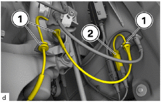
Connect the front skid control sensor wire in the brackets (1).
Connect the connector (2) and lock.
17.CONNECT SENSOR WIRE (w/ AVS)
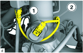
Attach the sensor wire in the holder (2).
Connect the connectors (1) and lock.
53876F
18.INSTALL FRONT NO. 2 FENDER LINER
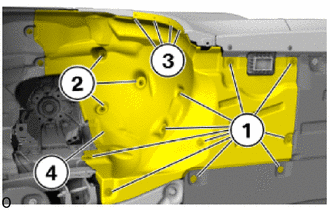
Insert the front No. 2 fender liner (4).
Tighten the screws (1) and nuts (2).
- Torque:
- Screw : 2.6 N*m (27 kgf*cm, 23 in.*lbf)
- Nut : 2.6 N*m (27 kgf*cm, 23 in.*lbf)
Replace the plastic rivet (3).
Insert the plastic rivet (3).
53879
19.INSTALL FRONT FENDER LINER
53896B
20.INSTALL FRONT FENDER SPLASH FRONT SHIELD
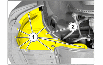
Insert the front fender splash front shield (2) at the side.
Tighten the screws (1).
- Torque:
- 2.6 N*m (27 kgf*cm, 23 in.*lbf)
21.INSTALL FRONT WHEEL
22.INSPECT AND ADJUST FRONT WHEEL ALIGNMENT