B48 ENGINE MECHANICAL ENGINE MOUNTING INSTALLATION
PROCEDURE

 12311
1.INSTALL NO. 1 FRONT ENGINE MOUNTING BRACKET RH
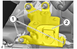
Install the No. 1 front engine mounting bracket RH (2).
Tighten the E12 bolts (1).
- Torque:
- 38 N*m (387 kgf*cm, 28 ft.*lbf)
12315
2.INSTALL NO. 1 FRONT ENGINE MOUNTING BRACKET LH
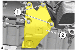
Install the No. 1 front engine mounting bracket LH (2).
Tighten the E12 bolts (1).
- Torque:
- 38 N*m (387 kgf*cm, 28 ft.*lbf)
12361
3.INSTALL FRONT ENGINE MOUNTING INSULATOR LH
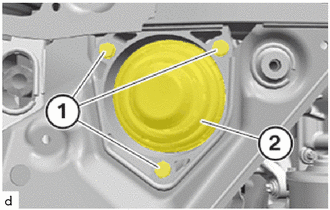
Install the front engine mounting insulator LH (2).
Tighten the bolts (1).
- Torque:
- 19 N*m (194 kgf*cm, 14 ft.*lbf)
12361
4.INSTALL FRONT ENGINE MOUNTING INSULATOR RH
- HINT:
-
Use the same procedure as for the LH side.
51201
5.INSTALL FRONT SUSPENSION CROSSMEMBER SUB-ASSEMBLY
48630
6.INSTALL FRONT UPPER SUSPENSION ARM ASSEMBLY LH (w/ Front Suspension Member Bracket)
Position front upper suspension arm assembly LH at the front suspension crossmember sub-assembly.
Replace the 18 mm bolt.
Tighten 18 mm bolt.
- Torque:
- 100 N*m (1020 kgf*cm, 74 ft.*lbf)
- NOTICE:
-
Tighten the 18 mm bolt connection in the normal position.
Using SST, tighten the 18 mm bolt an additional 90°.
- SST
- 09900-WA010
- HINT:
- ·
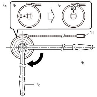 2.99,1.271 3.156,1.188 false 2.906,2.094 2.906,1.76 false 0.875,3 1.208,3 false 0.104,0.125 0.417,0.281 0.313,0.156 10 false *a 0.448,0.125 0.76,0.281 0.313,0.156 10 false *b 2.042,0.125 2.354,0.281 0.313,0.156 10 false *c 3.188,1.073 3.427,1.271 0.24,0.198 10 false *d 2.854,2.146 3.167,2.302 0.313,0.156 10 false *b 1.302,2.927 1.615,3.083 0.313,0.156 10 false *c
*a Example *b Before Tightening *c After Tightening *d Magnetic Portion
·The magnetic portion is used to secure the gauge to the vehicle.
·After first adjusting the needle of the gauge to 0°, tighten to the specified angle.
·Perform the work procedure carefully so that the gauge, etc. does not become tilted.
48610
7.INSTALL FRONT UPPER SUSPENSION ARM ASSEMBLY RH (w/ Front Suspension Member Bracket)
- HINT:
-
Use the same procedure as for the LH side.
82161
8.INSTALL FLOOR WIRE
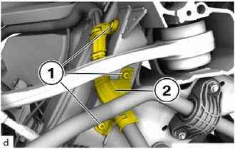
Position the wire harness mounting (2) with the wire harness.
Tighten the T25 screws (1).
- Torque:
- 8.0 N*m (82 kgf*cm, 71 in.*lbf)
52822
9.INSTALL AIR INTAKE DUCT LH
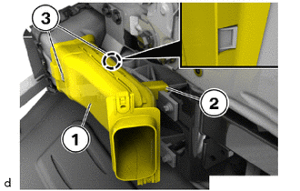
Position air intake duct LH (1) with the guide (2) correctly and clip into the latch mechanisms (3).
52821
10.INSTALL AIR INTAKE DUCT RH
- HINT:
-
Use the same procedure as for the LH side.
45220
11.INSTALL STEERING INTERMEDIATE SHAFT ASSEMBLY
12.REMOVE ENGINE SUPPORT BRIDGE
for Type A:
Click hereSuspension>FRONT SUSPENSION>FRONT SUSPENSION MEMBER>INSTALLATION
for Type B:
Click hereSuspension>FRONT SUSPENSION>FRONT SUSPENSION MEMBER>INSTALLATION
13.REMOVE ENGINE HANGER
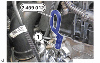
Unscrew the bolts of the special tool 2 459 012.
- SST
- 09200-WA610
Feed out the special tool 2 459 012 at the cylinder head and remove.
- SST
- 09200-WA610
25051
14.INSTALL EXHAUST MANIFOLD CONVERTER SUB-ASSEMBLY
12361
15.INSTALL FRONT ENGINE MOUNTING INSULATOR LH
- NOTICE:
-
In order to prevent play, lower the engine completely before screwing the engine mount and engine mounting bracket.
Tighten down E14 bolt.
- Torque:
- 100 N*m (1020 kgf*cm, 74 ft.*lbf)
12361
16.INSTALL FRONT ENGINE MOUNTING INSULATOR RH
- NOTICE:
-
In order to prevent play, lower the engine completely before screwing the engine mount and engine mounting bracket.
Tighten down E14 bolt.
- Torque:
- 100 N*m (1020 kgf*cm, 74 ft.*lbf)
53879
17.INSTALL FRONT FENDER LINER LH
53878
18.INSTALL FRONT FENDER LINER RH
- HINT:
-
Use the same procedure as for the LH side.
51219
19.INSTALL FRONT SUSPENSION MEMBER LOWER PROTECTOR
53826A
20.INSTALL FRONT FENDER UPPER PROTECTOR LH
53825A
21.INSTALL FRONT FENDER UPPER PROTECTOR RH
- HINT:
-
Use the same procedure as for the LH side.
22.INSTALL WHEEL ASSEMBLY
23.INSTALL ENGINE ROOM ECM BOX
24.INSTALL NO. 1 INTEGRATION RELAY
12601B
25.INSTALL NO. 1 ENGINE COVER SUB-ASSEMBLY
26.REMOVE AND INSTALL BONNET HOOD SUPPORT ASSEMBLY
27.CONNECT CABLE TO NEGATIVE BATTERY TERMINAL
28.INSPECT AIRBAG FOR FUNCTION
29. START-UP OF ELECTROMECHANICAL STEERING
30.INSPECT STRAIGHT-AHEAD DRIVING POSITION OF THE STEERING WHEEL
31.INSPECT AND ADJUST FRONT WHEEL ALIGNMENT