B58 ENGINE MECHANICAL ENGINE INSTALLATION POSITION REMOVAL
PROCEDURE

 1.DISCONNECT CABLE FROM NEGATIVE BATTERY TERMINAL
Click hereGeneral>MAINTENANCE>B58 BATTERY>REMOVAL
12601B
2.REMOVE NO. 1 ENGINE COVER SUB-ASSEMBLY
3.REMOVE AND INSTALL HOOD SUPPORT ASSEMBLY
4.REMOVE NO. 1 INTEGRATION RELAY
5.REMOVE ENGINE ROOM ECM BOX
53826A
6.REMOVE FRONT UPPER FENDER PROTECTOR LH
53825A
7.REMOVE FRONT UPPER FENDER PROTECTOR RH
- HINT:
-
Use the same procedure described for the LH side.
8.REMOVE WHEEL ASSEMBLY
51219
9.REMOVE FRONT SUSPENSION MEMBER LOWER PROTECTOR
45220
10.REMOVE STEERING INTERMEDIATE SHAFT ASSEMBLY
11.INSTALL ENGINE SUPPORT BRIDGE
for Type A:
Click hereSuspension>FRONT SUSPENSION>FRONT SUSPENSION MEMBER>REMOVAL
for Type B:
Click hereSuspension>FRONT SUSPENSION>FRONT SUSPENSION MEMBER>REMOVAL
12315
12.SEPARATE NO. 1 FRONT ENGINE MOUNTING BRACKET LH
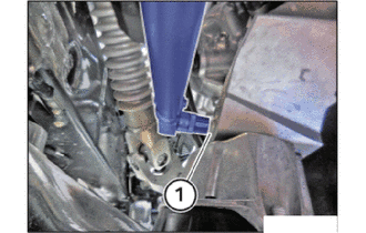
Release the E14 bolt (1) from the top.
12311
13.SEPARATE NO. 1 FRONT ENGINE MOUNTING BRACKET RH
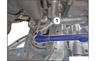
Release the E14 bolt (1) from the top.
14.SUPPORT ENGINE ASSEMBLY
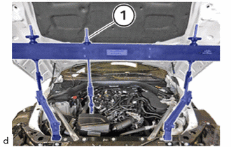
for Type A:
Raise the engine by turning the spindle (1) by 10 mm.
for Type B:
Raise the engine by turning the chain block by 10 mm.
15.REMOVE ENGINE SUPPORT BRIDGE
for Type A:
Turn the spindle (1) to lower the engine until the engine support arms rest completely flat on the engine mounts.
Remove the engine bridge with the help from another person.
for Type B:
Turn the chain block to lower the engine until the engine support arms rest completely flat on the engine mounts.
Remove the engine support bridge with the help from another person.
- NOTICE:
-
Prevent SST from contacting the vehicle body or windshield glass.
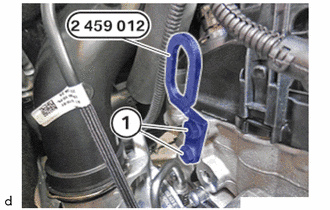
Unscrew the bolts (1) of the special tool 2 459 012.
- SST
- 09200-WA610
Feed out the special tool 2 459 012 at the cylinder head and remove.
- SST
- 09200-WA610