FRONT SUSPENSION FRONT SUSPENSION MEMBER REMOVAL
CAUTION / NOTICE / HINT
- CAUTION:
- ·
Motor vehicle may slip off the vehicle hoist where components are supported.
Danger! Life-threatening injuries!
-Secure the vehicle hoist against lowering and lifting.
- ·
Vehicle may slip off the vehicle hoist if the vehicle hoist is handled incorrectly.
Danger! Life-threatening injuries!
-Observe safety information on raising the vehicle using a vehicle hoist.
-For additional information see:
Click hereGeneral>INTRODUCTION>REPAIR INSTRUCTION>VEHICLE LIFT AND SUPPORT LOCATIONS
- ·
Motor vehicle may slip off the vehicle hoist if the weight is distributed unevenly.
Danger! Life-threatening injuries!
-Ensure there is a specific weight compensation on the motor vehicle.
PROCEDURE

 1.DISCONNECT CABLE FROM NEGATIVE BATTERY TERMINAL (for B48)
Click hereGeneral>MAINTENANCE>B48 BATTERY>REMOVAL
2.DISCONNECT CABLE FROM NEGATIVE BATTERY TERMINAL (for B58)
Click hereGeneral>MAINTENANCE>B58 BATTERY>REMOVAL
3.REMOVE AND INSTALL HOOD SUPPORT ASSEMBLY
12601B
4.REMOVE NO. 1 ENGINE COVER SUB-ASSEMBLY (for B48)
12601B
5.REMOVE NO. 1 ENGINE COVER SUB-ASSEMBLY (for B58)
6.REMOVE INTEGRATION RELAY (for Engine Room Side)
7.REMOVE ENGINE ROOM ECU BOX (for B48)
8.REMOVE ENGINE ROOM ECU BOX (for B58)
9.REMOVE FRONT WHEEL
53826A
10.REMOVE FRONT FENDER UPPER PROTECTOR LH
53825A
11.REMOVE FRONT FENDER UPPER PROTECTOR RH
- HINT:
-
Use the same procedure as for the LH side.
51219
12.REMOVE FRONT SUSPENSION MEMBER LOWER PROTECTOR
53879
13.REMOVE FRONT FENDER LINER LH
53878
14.REMOVE FRONT FENDER LINER RH
- HINT:
-
Use the same procedure as for the LH side.
15.INSTALL ENGINE HANGER
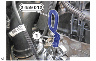
Guide in and position special tool 2 459 012 on cylinder head sub-assembly.
- SST
- 09200-WA610
Tighten the bolts (1) of special tool 2 459 012.
- SST
- 09200-WA610
- Torque:
- 21.5 N*m (219 kgf*cm, 16 ft.*lbf)
16.INSTALL ENGINE SUPPORT BRIDGE (for Type A)
- CAUTION:
- ·
Components connected to the engine joint or front suspension crossmember sub-assembly.
Danger of injury
-Check lifting eyes and engine mounting brackets for damage, e.g. cracks.
-Attach the component to correctly mounted engine joints or front suspension crossmember sub-assembly only.
-Exclusively lift the component, do not move it forwards, backwards or in transverse direction.
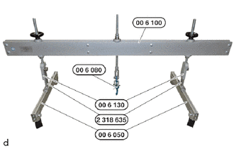
Prepared engine support bridge.
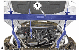
Screw special tools 0 496 852 (00 6 100), 2 209 122 (00 6 130), 2 318 635 and 0 496 430 (00 6 050) together.
- SST
- 09200-WA170
09200-WA690
09200-WA880
09200-WA910
Carefully position engine support bridge (1) with help from an auxiliary person.
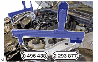
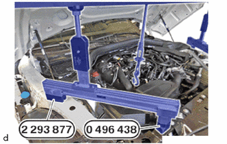
Make sure that the special tool 0 496 438 (00 6 053) from the set of special tools 0 496 430 (00 6 050) rests correctly on the front end on the left.
- SST
- 09200-WA170
Make sure that special tool 2 293 877 on the left is correctly positioned on the carrier support.
- SST
- 09900-WA110
Make sure that the special tool 0 496 438 (00 6 053) from the set of special tools 0 496 430 (00 6 050) rests correctly on the front end on the right.
- SST
- 09200-WA170
Make sure that special tool 2 293 877 on the right is correctly positioned on the carrier support.
- SST
- 09900-WA110
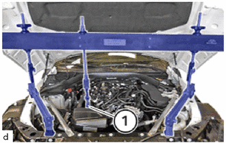
Slide the engine support bridge in longitudinal direction on the profile strips of the special tool 0 496 430 (00 6 050) and fix in the correct position.
- SST
- 09200-WA170
Slide the special tool 0 496 733 (00 6 080) in transverse direction and position and fix it above the engine mounting bracket (1).
- SST
- 09200-WA120
The special tool 0 496 733 (00 6 080) must be positioned above the engine mounting bracket (1).
- SST
- 09200-WA120
Attach the special tool 0 496 733 (00 6 080) in the engine mounting bracket (1).
- SST
- 09200-WA120
17.INSTALL ENGINE SUPPORT BRIDGE (for Type B)
Install SST to the vehicle body as shown in the illustration.
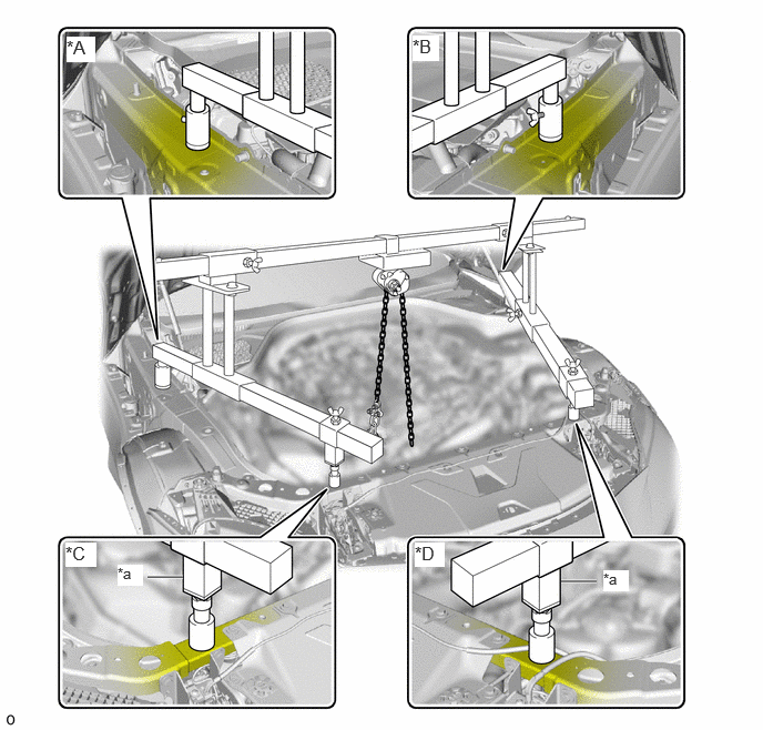
| *A | Area A | *B | Area B |
| *C | Area C | *D | Area D |
| *a | Support Shaft | - | - |
- SST
- 09940-10010
09940-10040
09940-10050
- CAUTION:
- ·
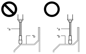 0.448,1.167 0.781,1.167 false 2.438,1.167 2.771,1.167 false 1.052,1.781 1.052,1.448 1.052,1.448 1.219,1.448 false 2.604,1.781 2.604,1.448 2.604,1.448 2.438,1.448 false 0.292,1.094 0.604,1.25 0.313,0.156 10 false *a 2.271,1.094 2.583,1.25 0.313,0.156 10 false *a 1.281,1.385 1.594,1.542 0.313,0.156 10 false *b 2.271,1.385 2.583,1.542 0.313,0.156 10 false *b
*a Support Shaft *b Area A, B, C and D
Make sure that no oil or grease is on the area A, B, C and D, and set the engine support bridge on the level surface of the area A, B, C and D.
·The engine support bridge may fall off if any oil or grease is still on or it is installed on the unlevel surface.
- NOTICE:
- ·
Prevent SST from contacting the vehicle body exterior and windshield glass.
·To prevent damage to the engine hood, place pieces of cloth between the engine hood and SST.
·Lightly shake SST by hand to make sure it is securely installed before performing work.
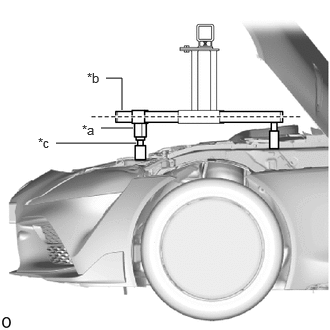
| *a | Support Shaft |
| *b | Sub Beam |
| *c | Threaded Portion |
Turn the threaded portion of each support shaft to adjust its height until the sub beams are parallel to the ground.
Install the chain block to the sling bracket.
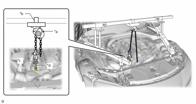
| *a | Chain Block | *b | Sling Bracket |
| *c | Fuse Shackle | *d | Shackle |
Connect the shackle to the engine hanger.
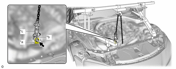
| *a | Engine Hanger | *b | Shackle |
| *c | Fuse Shackle | - | - |
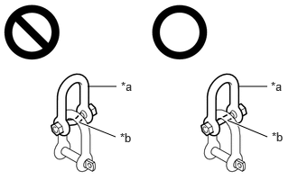
- CAUTION:
- ·
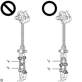 0.479,2.573 0.813,2.573 false 2.198,2.563 2.531,2.563 false 0.479,2.865 0.813,2.865 false 2.198,2.885 2.531,2.885 false 0.271,2.479 0.583,2.677 0.313,0.198 10 false *a 1.969,2.469 2.281,2.667 0.313,0.198 10 false *a 0.271,2.76 0.583,2.958 0.313,0.198 10 false *b 1.979,2.802 2.292,3 0.313,0.198 10 false *b
*a Fuse Shackle *b Shackle
Make sure the fuse shackle is on the chain block side and the shackle is on the engine hanger side as shown in the illustration so that the fuse bolt is visible and can be checked for deformation easily.
·If the fuse shackle is installed upside down, deformation of the fuse bolt will not be visible and cannot be used to tell if the load capacity of the engine support bridge has been exceeded. If the load capacity is exceeded, it may cause the engine support bridge to damage the vehicle and the engine assembly with automatic transmission assembly may fall.
· 2.75,1 3.083,1 false 1.01,1 1.344,1 false 0.917,1.417 1.333,1.583 true 2.635,1.396 3.083,1.583 true 1.396,0.917 1.708,1.073 0.313,0.156 10 false *a 1.385,1.51 1.698,1.667 0.313,0.156 10 false *b 3.125,0.917 3.354,1.083 0.229,0.167 10 false *a 3.135,1.5 3.354,1.667 0.219,0.167 10 false *b
*a Fuse Shackle *b Fuse Bolt
Make sure that the fuse bolt of the fuse shackle is free of damage, such as deformation or cracks. If damaged, replace the fuse shackle.
·If a deformed fuse bolt is used, it cannot be used to tell if the load capacity of the engine support bridge has been exceeded. If the load capacity is exceeded, it may cause the engine support bridge to damage the vehicle and the engine assembly with automatic transmission assembly may fall.
Adjust the positions of the chain block assembly, support brackets and main beam so that the chain of the chain block assembly is perpendicular to the main beam and the length of the main beam on the outer side of the support bracket LH and RH is the same as shown in the illustration.
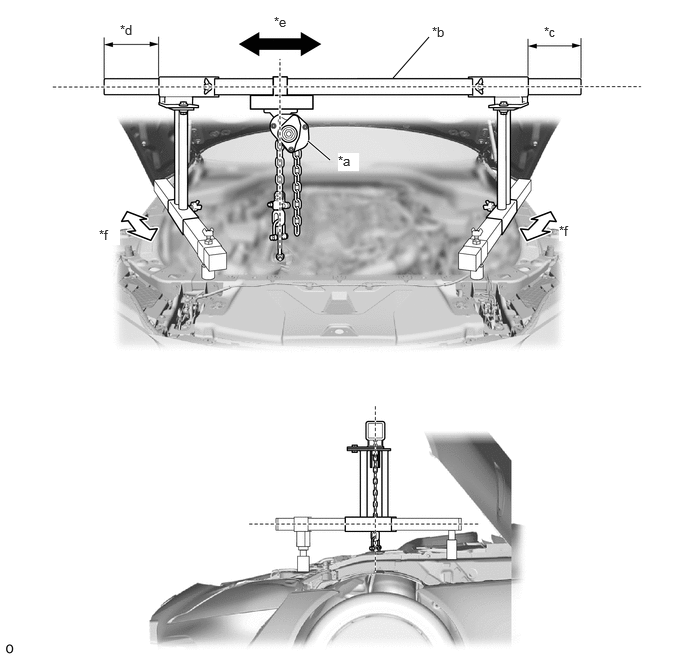
| *a | Chain Block | *b | Main Beam |
| *c | Dimension (A) | *d | Dimension (B) |
| *e | Right to Left Adjustment | *f | Front to Rear Adjustment |
- CAUTION:
- ·
To prevent the engine assembly with automatic transmission assembly from falling, make sure that the length of dimension (A) and dimension (B) are equal.
·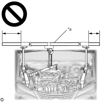 1.833,1.427 2.25,1.01 false 2.281,0.896 2.594,1.052 0.313,0.156 10 false *a
*a Main Beam
Do not perform any procedures if the length of dimension (A) and dimension (B) are not equal.
·Performing any procedure when the length of dimension (A) and dimension (B) are not equal may cause the engine assembly with automatic transmission assembly and engine support bridge to fall, possibly causing serious injury.
- NOTICE:
-
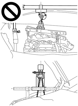
- ·
Do not perform any procedures if the chain of the chain block assembly is not straight.
·When removing the engine mount, if the chain of the chain block assembly is not straight, the engine assembly or automatic transmission assembly may contact the vehicle body.
Confirm the appropriate installation state of the engine support bridge and tighten the 6 wing bolts and 2 bolts.
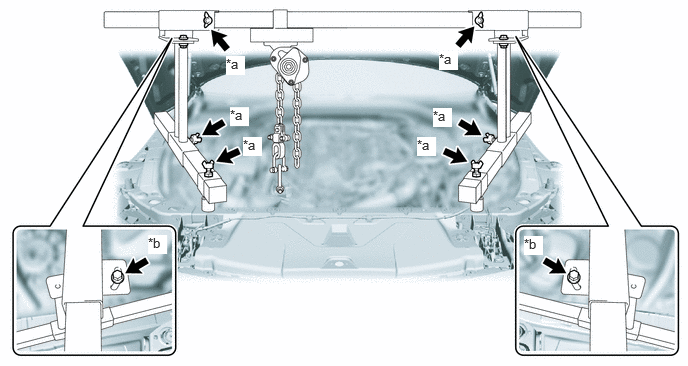
| *a | Wing Bolt | *b | Bolt |
- Torque:
- Bolt : 30 N*m (306 kgf*cm, 22 ft.*lbf)
- CAUTION:
- ·
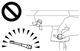
Do not perform any procedures before tightening the bolts to the specified torque.
·Performing procedures without tightening the bolts to the specified torque, may cause the engine support bridge to fall.
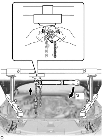
| *a | Turn |
Tighten the chain block assembly until it cannot be moved any further by hand.
- CAUTION:
-
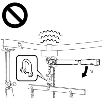 2.99,2.292 3.302,2.448 0.313,0.156 10 false *a
*a 41 N*m (418 kgf*cm, 30 ft.*lbf) or more
- ·
When suspending the engine assembly with automatic transmission assembly, do not tighten the chain block assembly more than 41 N*m (418 kgf*cm, 30 ft.*lbf).
·Tightening the chain block assembly more than 41 N*m (418 kgf*cm, 30 ft.*lbf) will cause the load capacity (400 kg (881.8 lb.)) to be exceeded and may cause damage to the engine support bridge and vehicle body.
12361
18.SEPARATE FRONT ENGINE MOUNTING INSULATOR LH
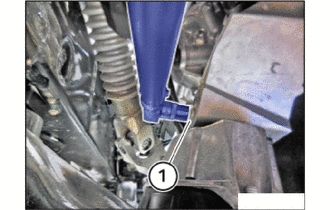
Release the E14 bolt (1) from the top.
12361
19.SEPARATE FRONT ENGINE MOUNTING INSULATOR RH
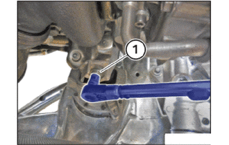
Release the E14 bolt (1) from the top.
20.SUPPORT ENGINE ASSEMBLY (for Type A)
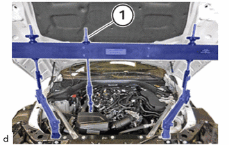
Raise the engine by turning the spindle (1) by 10 mm.
21.SUPPORT ENGINE ASSEMBLY (for Type B)
Raise the engine by turning the chain block by 10 mm.
52822
22.REMOVE AIR INTAKE DUCT LH
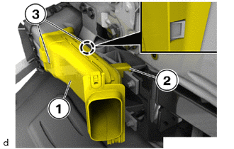
Lift air intake duct LH (1) with the guide (2), detach it from the latch mechanisms (3) to the rear and remove.
52821
23.REMOVE AIR INTAKE DUCT RH
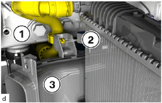
for B58:
Unclip coolant line (1) and bracket (2) from the air intake duct RH (3).
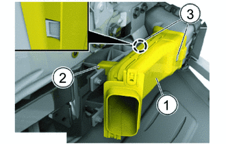
Lift air intake duct RH (1) with the guide (2), detach it from the latch mechanisms (3) to the rear and remove.
45220
24.DISCONNECT STEERING INTERMEDIATE SHAFT ASSEMBLY
48810
25.SEPARATE FRONT STABILIZER LINK ASSEMBLY LH
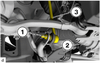
Loosen the 16 mm nut (1), if necessary, counter hold the T30 "TORX" socket wrench.
Loosen the front stabilizer link assembly LH (3) from the front stabilizer bar (2).
48820B
26.SEPARATE FRONT STABILIZER LINK ASSEMBLY RH
- HINT:
-
Use the same procedure as for the LH side.
27.SEPARATE COOLANT HOSE (for B58)
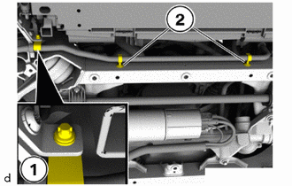
Loosen E8 bolts (1).
Release both holders (2) from the front suspension crossmember sub-assembly.
- NOTICE:
- ·
The coolant hose is not removed.
·The coolant circuit is not opened.
45047
28.DISCONNECT TIE ROD END SUB-ASSEMBLY LH
45046
29.DISCONNECT TIE ROD END SUB-ASSEMBLY RH
- HINT:
-
Use the same procedure as for the LH side.
48811
30.REMOVE FRONT STABILIZER BAR
31.REMOVE STEERING LINK ASSEMBLY
32.SEPARATE WIRE HARNESS
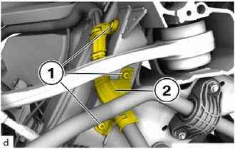
Loosen T25 screws (1).
Remove the wire harness mounting (2) with wire harness, move it to the side and secure it in place.
33.SEPARATE FRONT LOWER SUSPENSION ARM ASSEMBLY LH
- NOTICE:
- ·
Component damage caused by striking tools.
Brute force can result in component damage.
-Only use those tools intended for the work.
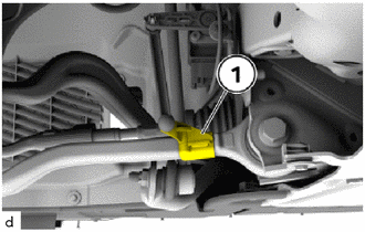
w/ Height Control Sensor:
Release the front height control sensor link sub-assembly (1) on the front lower suspension arm assembly LH.
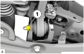
Using a 18 mm deep socket wrench, unscrew the nut (1) and remove the 18 mm bolt to the rear.
Release the front lower suspension arm assembly LH from the front suspension crossmember sub-assembly.
34.SEPARATE FRONT LOWER SUSPENSION ARM ASSEMBLY RH
- HINT:
-
Use the same procedure as for the LH side.
48630
35.REMOVE FRONT UPPER SUSPENSION ARM ASSEMBLY LH
w/ Front Suspension Member Bracket:
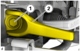
Loosen 18 mm bolt (1).
Remove the front suspension member bracket sub-assembly LH (2).
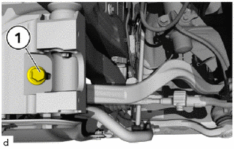
w/o Front Suspension Member Bracket:
Loosen 18 mm bolt (1).
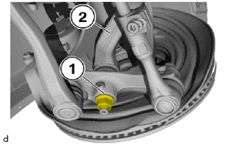
Loosen the nut (1), if necessary, counter-hold the T40 "TORX" socket wrench.
Remove front upper suspension arm assembly LH (2).
48610
36.REMOVE FRONT UPPER SUSPENSION ARM ASSEMBLY RH
- HINT:
-
Use the same procedure as for the LH side.
51201
37.REMOVE FRONT SUSPENSION CROSSMEMBER SUB-ASSEMBLY
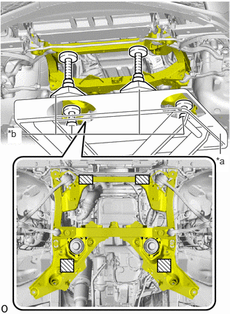
| *a | Engine Lifter |
| *b | Attachment |

|
Attachment placement location |
Support the front suspension crossmember sub-assembly with an engine lifter using 4 attachments or equivalent tools as shown in the illustration.
- CAUTION:
-
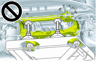
- ·
The front suspension crossmember sub-assembly is a very heavy component. Make sure that it is supported securely.
·If the front suspension crossmember sub-assembly is not securely supported, it may drop, resulting in serious injury.
- NOTICE:
-
Use attachments to keep the front suspension crossmember sub-assembly level.
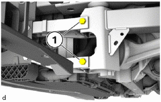
Remove the E11 bolts (1).
- HINT:
-
Perform the operations on the left and right side.
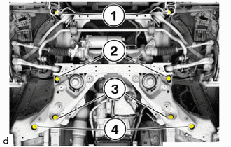
Remove the E14 bolts (1), E18 bolts (2), bolts (3) and E18 bolts (4)
Slowly lower the front suspension crossmember sub-assembly.
- NOTICE:
-
When lowering the front suspension crossmember sub-assembly, be careful not to damage the vehicle body or other components installed to the vehicle.
38.REMOVE CLIP
- HINT:
-
Perform the operations on the left and right side.
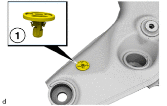
Remove the clip (1).
12361
39.REMOVE FRONT ENGINE MOUNTING INSULATOR LH
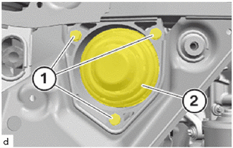
Loosen the bolts (1).
Remove the front engine mounting insulator LH (2).
12361
40.REMOVE FRONT ENGINE MOUNTING INSULATOR RH
- HINT:
-
Use the same procedure as for the LH side.