B58 ENGINE MECHANICAL CYLINDER HEAD GASKET REMOVAL
PROCEDURE

 13050
1.REMOVE CAMSHAFT TIMING GEAR ASSEMBLY
13070A
2.REMOVE CAMSHAFT TIMING EXHAUST GEAR ASSEMBLY
3.REMOVE WHEEL ASSEMBLY
45047
4.DISCONNECT TIE ROD END SUB-ASSEMBLY LH
45046
5.DISCONNECT TIE ROD END SUB-ASSEMBLY RH
- HINT:
-
Use the same procedure as for the LH side.
51219
6.REMOVE FRONT SUSPENSION MEMBER LOWER PROTECTOR
45220
7.REMOVE STEERING INTERMEDIATE SHAFT ASSEMBLY
8.REMOVE STEERING LINK ASSEMBLY
15474
9.REMOVE OUTLET TURBO OIL PIPE
25051
10.REMOVE EXHAUST MANIFOLD CONVERTER SUB-ASSEMBLY
17293
11.REMOVE TURBOCHARGER STAY
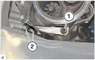
Loosen T40 bolt (1).
Release T40 bolts (2) and remove the turbocharger stay.
17167
12.REMOVE NO.1 EXHAUST MANIFOLD HEAT INSULATOR (for 6 Port Type)
11101
13.REMOVE CYLINDER HEAD SUB-ASSEMBLY
- CAUTION:
- ·
Heavy component.
Heavy components can lead to injury or damage.
-Remove and install heavy components with the aid of another person/other persons.
- HINT:
-
Collect and dispose of emerging fluids. Observe country-specific waste disposal regulations.
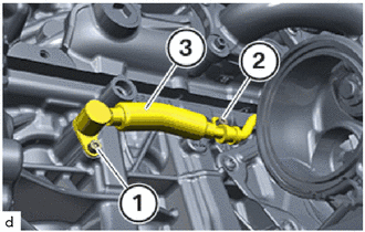
Loosen T30 bolts (1) and (2).
Guide the No. 1 turbo water pipe sub-assembly for turbocharger sub-assembly (3) from the cylinder block sub-assembly and place it aside.
Catch and dispose of escaping coolant.
for 2 Port Type:
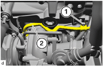
Release T30 bolt (1) on the holder of No. 2 turbo water pipe sub-assembly (2).
Have a rag ready and catch any engine oil that may emerge.
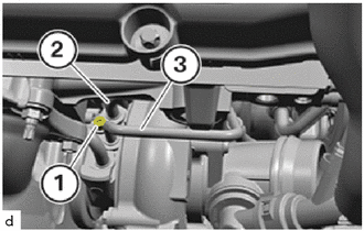
Loosen T30 bolt (1).
Guide out No. 2 turbo water pipe sub-assembly and No. 1 turbo water pipe sub-assembly (2) for the turbocharger sub-assembly and place it aside.
Guide out inlet turbo oil pipe sub-assembly (3) for the turbocharger sub-assembly and place it aside.
Collect and dispose of emerging fluids.
6 Port Type:
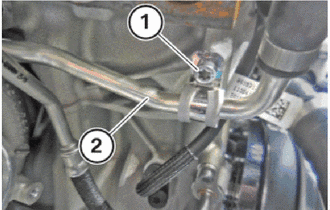
Unscrew screw (1) on the No. 2 turbo water pipe sub-assembly (2).
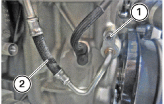
Loosen the screw (1).
Remove the inlet turbo oil pipe sub-assembly (2).
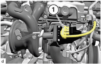
Unlock plug connection (1) and disconnect.
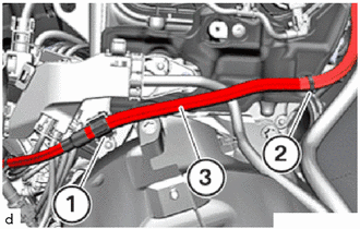
Unlock and release clamps (1) and (2).
Feed out alternator positive battery cable (3) and put to one side.
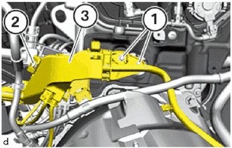
Loosen E8 bolts (1).
Unlock lock (2).
Guide out transmission wire (3) and place it aside.
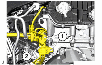
Loosen T30 bolts (1).
Guide out the wiring harness section for engine wire (2) and place to one side.
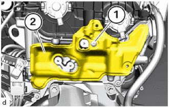
Loosen T30 bolt (1).
Guide out and remove the No. 4 engine cover (2).
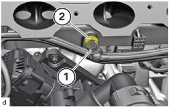
Unlock and disconnect plug connection (1) on coolant temperature sensor (2).
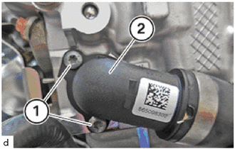
Loosen T30 bolts (1).
Feed out No. 2 water by-pass hose (2) and place to one side.
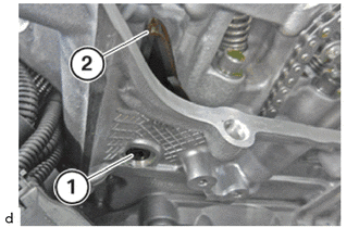
Release the T45 bearing journal (1) from the No. 1 chain vibration damper (2).
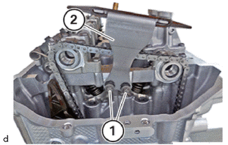
Loosen E10 bolts (1).
Guide out the chain damper guide (2) and remove.
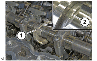
Rotate intake camshaft sub-assembly, if necessary in the position shown.
The recess (2) must point upwards.
Loosen 3 mm hexagon bolt (1).
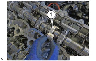
Slide camshaft sensor wheel (1) in the direction of cylinder 1 and guide it out from the intake camshaft sub-assembly.
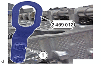
Guide in and position special tool 2 459 012 on cylinder head sub-assembly.
- SST
- 09200-WA610
Tighten the bolts (1) of special tool 2 459 012 .
- SST
- 09200-WA610
- Torque:
- 21.5 N*m (219 kgf*cm, 16 ft.*lbf)
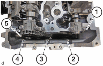
Loosen E10 bolts (1) to (5).
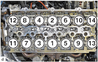
Undo the T60 bolts in the order (14) to (1) .
- NOTICE:
-
- ·
Damage to the guide rails.
Large amounts of force may damage the guide rails of the timing chain.
-Make sure not to damage the guide rail with the cylinder head sub-assembly when removing and installing the cylinder head sub-assembly.
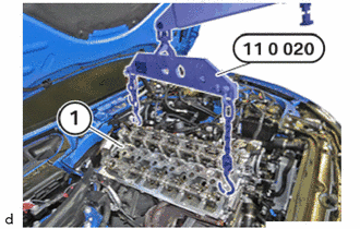
Lift out cylinder head sub-assembly (1) and the turbocharger sub-assembly with an auxiliary person, the workshop crane and special tool 0 490 567 (11 0 020).
- SST
- 09200-WA860
11115
14.REMOVE CYLINDER HEAD GASKET
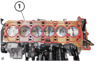
Thread out and remove cylinder head gasket (1).
15. SEALING OIL DUCT
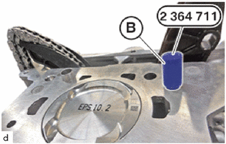
Seal the oil duct using special tool (B) from the set of special tools 2 364 711 .
- SST
- 09200-WA530
16. CLEAN SEALING SURFACE
- NOTICE:
- ·
Damage to the surface.
The use of metal-cutting tools (e.g. emery cloth) to clean the surfaces can damage them and lead to leaks or engine damage.
-Do not use any metal-cutting tools.
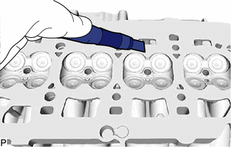
Remove coarse backlogs from the sealing surfaces of the cylinder head sub-assembly.
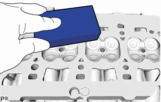
Remove fine backlogs from the sealing surfaces of the cylinder head sub-assembly.
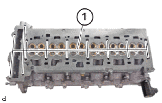
Clean all blind holes (1) of the cylinder head sub-assembly.
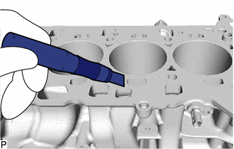
Remove coarse backlogs from the sealing surfaces of the cylinder block sub-assembly.
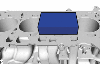
Remove fine backlogs from the sealing surfaces of the cylinder block sub-assembly.
- CAUTION:
- ·
Swirling dirt particles caused by compressed air.
Danger of injury!
-Collect dirt particles, e.g. when blowing out, use cloth to do so.
-Wear safety goggles.
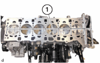
Clean all threaded holes (1) of the cylinder block sub-assembly with compressed air.
Remove special tool (B) contained in the set of special tools 2 364 711 .
- SST
- 09200-WA530