PARKING BRAKE PARKING BRAKE CABLE INSTALLATION
PROCEDURE

 46452B
1.INSTALL NO. 2 CABLE SUPPORT BRACKET
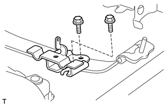
Install the No. 2 cable support bracket with the 2 bolts.
- Torque:
- 19 N*m (194 kgf*cm, 14 ft.*lbf)
46301
2.INSTALL PARKING BRAKE INTERMEDIATE LEVER SUB-ASSEMBLY
Apply MP grease to the moving parts of the parking brake intermediate lever sub-assembly.
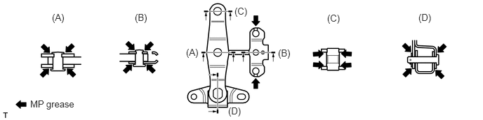
Apply MP grease to the areas where the cables contact the parking brake intermediate lever sub-assembly.
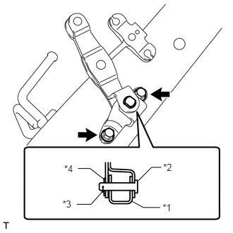
Install the parking brake intermediate lever sub-assembly to the parking brake intermediate lever bracket with the clip, washer and pin.
| *1 | Parking Brake Intermediate Lever Bracket |
| *2 | Pin |
| *3 | Clip |
| *4 | Washer |
Install the parking brake intermediate lever sub-assembly with parking brake intermediate lever bracket with the 2 bolts.
- Torque:
- 19 N*m (194 kgf*cm, 14 ft.*lbf)
46430
3.INSTALL NO. 3 PARKING BRAKE CABLE ASSEMBLY
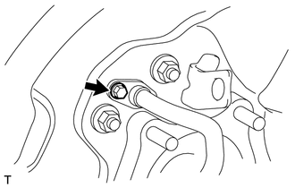
Install the No. 3 parking brake cable assembly to the rear axle carrier with the bolt.
- Torque:
- 8.0 N*m (82 kgf*cm, 71 in.*lbf)
Connect the No. 3 parking brake cable assembly to the parking brake intermediate lever sub-assembly (labeled C) and install the 6 bolts (labeled A and B).
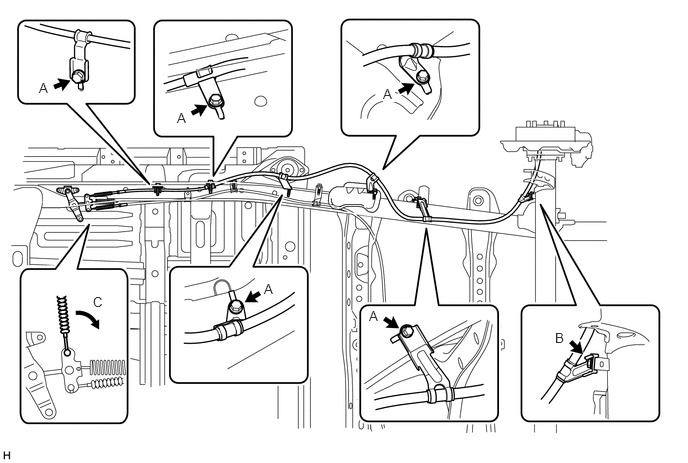
- Torque:
- for bolt A : 19 N*m (194 kgf*cm, 14 ft.*lbf)
- for bolt B : 14 N*m (138 kgf*cm, 10 ft.*lbf)
- NOTICE:
-
Do not bend and twist the parking brake cable.
4.INSTALL PARKING BRAKE SHOE LEVER LH
46590
5.INSTALL NO. 2 PARKING BRAKE SHOE ASSEMBLY LH
46580
6.INSTALL NO. 1 PARKING BRAKE SHOE ASSEMBLY LH
7.INSTALL PARKING BRAKE SHOE RETURN SPRING LH
8.CHECK PARKING BRAKE INSTALLATION
42431
9.INSTALL REAR DISC LH
10.ADJUST PARKING BRAKE SHOE CLEARANCE
11.CONNECT REAR DISC BRAKE CYLINDER ASSEMBLY LH
12.INSTALL REAR WHEEL LH
46420
13.INSTALL NO. 2 PARKING BRAKE CABLE ASSEMBLY
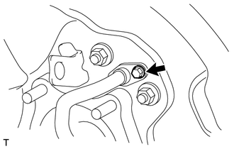
Install the No. 2 parking brake cable assembly to the rear axle carrier with the bolt.
- Torque:
- 8.0 N*m (82 kgf*cm, 71 in.*lbf)
Install the No. 2 parking brake cable clamp with the bolt (labeled A).
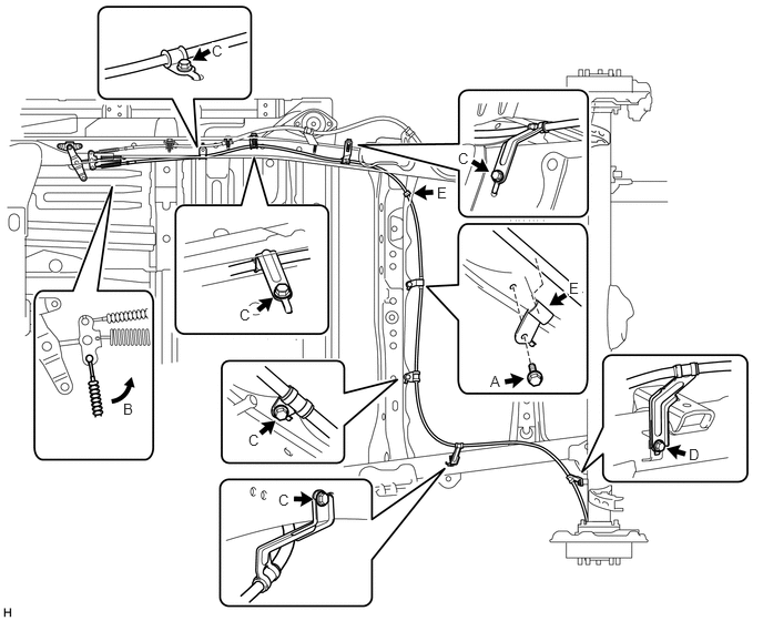
- Torque:
- 19 N*m (194 kgf*cm, 14 ft.*lbf)
Connect the No. 2 parking brake cable assembly to the parking brake intermediate lever sub-assembly (labeled B) and install the 6 bolts (labeled C and D).
- NOTICE:
-
Do not bend and twist the parking brake cable.
- Torque:
- for bolt C : 19 N*m (194 kgf*cm, 14 ft.*lbf)
- for bolt D : 14 N*m (138 kgf*cm, 10 ft.*lbf)
Connect the No. 2 parking brake cable assembly to the 2 No. 2 parking brake clamps (labeled E).
46458A
14.INSTALL NO. 2 CABLE RETAINER
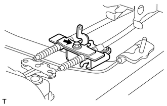
Install the No. 2 cable retainer with the bolt.
- Torque:
- 13 N*m (127 kgf*cm, 9 ft.*lbf)
46301A
15.INSTALL INTERMEDIATE LEVER TENSION SPRING
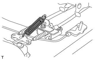
Install the intermediate lever tension spring.
16.INSTALL PARKING BRAKE SHOE LEVER RH
- HINT:
-
Use the same procedures described for the LH side.
46550
17.INSTALL NO. 2 PARKING BRAKE SHOE ASSEMBLY RH
- HINT:
-
Use the same procedures described for the LH side.
46540
18.INSTALL NO. 1 PARKING BRAKE SHOE ASSEMBLY RH
- HINT:
-
Use the same procedures described for the LH side.
19.INSTALL PARKING BRAKE SHOE RETURN SPRING RH
- HINT:
-
Use the same procedures described for the LH side.
20.CHECK PARKING BRAKE INSTALLATION
42431
21.INSTALL REAR DISC RH
- HINT:
-
Use the same procedures described for the LH side.
22.ADJUST PARKING BRAKE SHOE CLEARANCE
23.CONNECT REAR DISC BRAKE CYLINDER ASSEMBLY RH
- HINT:
-
Use the same procedures described for the LH side.
24.INSTALL REAR WHEEL RH
46410
25.INSTALL NO. 1 PARKING BRAKE CABLE ASSEMBLY (for 3700 mm [12 ft. 1.7 in.] Wheelbase Type)
Install the No. 1 cable support bracket with the 3 bolts (labeled A).
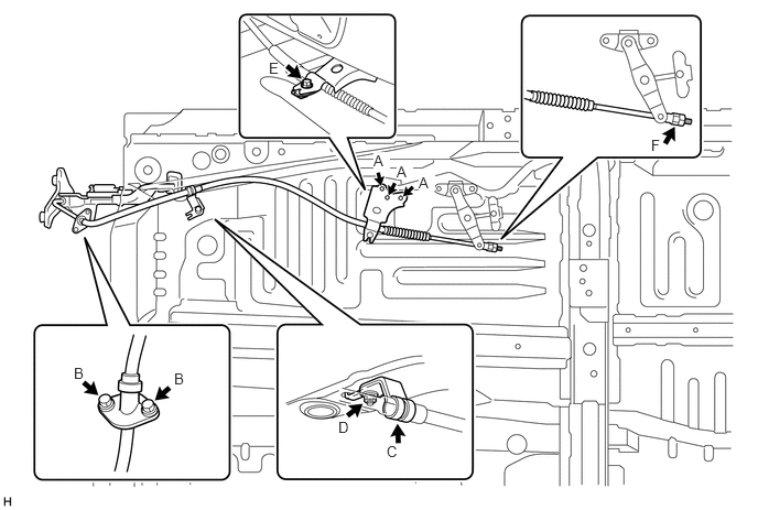
- Torque:
- 19 N*m (194 kgf*cm, 14 ft.*lbf)
Install the No. 1 parking brake cable assembly to the inside of the vehicle with the 2 bolts (labeled B).
- Torque:
- 5.4 N*m (55 kgf*cm, 48 in.*lbf)
Connect the No. 1 parking brake cable clamp (labeled C) to the No. 1 parking brake cable assembly.
Install the No. 1 parking brake cable clamp with the nut (labeled D).
- Torque:
- 5.4 N*m (55 kgf*cm, 48 in.*lbf)
Install the No. 1 parking brake cable assembly and cable retainer with the bolt (labeled E).
- Torque:
- 13 N*m (127 kgf*cm, 9 ft.*lbf)
Temporarily install the adjustment nut and lock nut (labeled F).
- NOTICE:
-
Do not bend and twist the parking brake cable.
- HINT:
-
The nuts will be tightened to a torque specification in the "ADJUST PARKING BRAKE PEDAL TRAVEL" procedure.
46410
26.INSTALL NO. 1 PARKING BRAKE CABLE ASSEMBLY (for 4180 mm [13 ft. 8.6 in.] Wheelbase Type)
Install the No. 1 cable support bracket with the 3 bolts (labeled A).
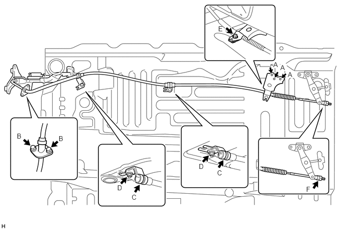
- Torque:
- 19 N*m (194 kgf*cm, 14 ft.*lbf)
Install the No. 1 parking brake cable assembly to the inside of the vehicle with the 2 bolts (labeled B).
- Torque:
- 5.4 N*m (55 kgf*cm, 48 in.*lbf)
Connect the 2 No. 1 parking brake cable clamps (labeled C) to the No. 1 parking brake cable assembly.
Install the 2 No. 1 parking brake cable clamps with the 2 nuts (labeled D).
- Torque:
- 5.4 N*m (55 kgf*cm, 48 in.*lbf)
Install the No. 1 parking brake cable assembly and cable retainer with the bolt (labeled E).
- Torque:
- 13 N*m (127 kgf*cm, 9 ft.*lbf)
Temporarily install the adjustment nut and lock nut (labeled F).
- NOTICE:
-
Do not bend and twist the parking brake cable.
- HINT:
-
The nuts will be tightened to a torque specification in the "ADJUST PARKING BRAKE PEDAL TRAVEL" procedure.
17410
27.INSTALL FRONT NO. 2 EXHAUST PIPE ASSEMBLY
for 1UR-FE:
Install the front No. 2 exhaust pipe (See page Engine / Hybrid System>1UR-FE EXHAUST>EXHAUST PIPE>INSTALLATION).
for 3UR-FE:
Install the front No. 2 exhaust pipe (See page Engine / Hybrid System>3UR-FE EXHAUST>EXHAUST PIPE>INSTALLATION).
for 3UR-FBE:
Install the front No. 2 exhaust pipe (See page Engine / Hybrid System>3UR-FBE EXHAUST>EXHAUST PIPE>INSTALLATION).
28.CONNECT NO. 1 PARKING BRAKE CABLE ASSEMBLY
29.SETTLE PARKING BRAKE SHOE AND DISC
30.CHECK PARKING BRAKE PEDAL TRAVEL
31.ADJUST PARKING BRAKE PEDAL TRAVEL
73900
32.INSTALL LOWER NO. 1 INSTRUMENT PANEL AIRBAG ASSEMBLY
55046A
33.INSTALL LOWER INSTRUMENT PANEL FINISH PANEL SUB-ASSEMBLY LH
55318C
34.INSTALL INSTRUMENT SIDE PANEL LH
35.CONNECT CABLE TO NEGATIVE BATTERY TERMINAL
36.CHECK SRS WARNING LIGHT
Check the SRS warning light (See page Vehicle Interior>SUPPLEMENTAL RESTRAINT SYSTEMS>AIRBAG SYSTEM>DIAGNOSIS SYSTEM).
37.INSPECT FOR EXHAUST GAS LEAK
If gas is leaking, tighten the areas necessary to stop the leak. Replace damaged parts as necessary.