METER / GAUGE / DISPLAY COMBINATION METER INSTALLATION
PROCEDURE

 83100
1.INSTALL COMBINATION METER ASSEMBLY
Pass the combination meter assembly between the steering wheel assembly and instrument panel.
Connect the connector and attach the wire harness clamp.
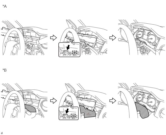
| *A | for Column Shift Type | *2 | for Floor Shift Type |
Install the combination meter assembly with the 4 screws.
55410C
2.INSTALL INSTRUMENT CLUSTER FINISH PANEL ASSEMBLY
for Column Shift Type:
(See page Vehicle Interior>INTERIOR PANEL>INSTRUMENT PANEL SAFETY PAD(for Column Shift Type)>INSTALLATION)
for Floor Shift Type:
(See page Vehicle Interior>INTERIOR PANEL>INSTRUMENT PANEL SAFETY PAD(for Floor Shift Type)>INSTALLATION)
55471A
3.INSTALL INSTRUMENT CLUSTER FINISH PANEL ORNAMENT
for Column Shift Type:
(See page Vehicle Interior>INTERIOR PANEL>INSTRUMENT PANEL SAFETY PAD(for Column Shift Type)>INSTALLATION)
for Floor Shift Type:
(See page Vehicle Interior>INTERIOR PANEL>INSTRUMENT PANEL SAFETY PAD(for Floor Shift Type)>INSTALLATION)
55447C
4.INSTALL NO. 2 SWITCH HOLE BASE
45286B
5.INSTALL UPPER STEERING COLUMN COVER (for Column Shift Type)
45287
6.INSTALL LOWER STEERING COLUMN COVER (for Column Shift Type)
55474C
7.INSTALL NO. 1 INSTRUMENT CLUSTER FINISH PANEL GARNISH
55046A
8.INSTALL LOWER INSTRUMENT PANEL FINISH PANEL SUB-ASSEMBLY LH
62112
9.INSTALL COWL SIDE TRIM BOARD LH
67914
10.INSTALL FRONT DOOR SCUFF PLATE LH
for Double Cab:
(See page Vehicle Interior>INTERIOR>ROOF HEADLINING(for Double Cab)>INSTALLATION)
for CrewMax:
(See page Vehicle Interior>INTERIOR>ROOF HEADLINING(for CrewMax)>INSTALLATION)
for Regular Cab:
(See page Vehicle Interior>INTERIOR>ROOF HEADLINING(for Regular Cab)>INSTALLATION)
55479B
11.INSTALL LOWER CENTER INSTRUMENT COVER (for Column Shift Type)
55318C
12.INSTALL INSTRUMENT SIDE PANEL LH
55061
13.INSTALL NO. 1 INSTRUMENT PANEL REGISTER SUB-ASSEMBLY
14.CONNECT CABLE TO NEGATIVE BATTERY TERMINAL
- NOTICE:
-
When disconnecting the cable, some systems need to be initialized after the cable is reconnected (See page General>INTRODUCTION>REPAIR INSTRUCTION>INITIALIZATION).
15.RESTORE AUTOAWAY/RETURN FUNCTION (for Power Tilt and Power Telescopic Steering Column)
Restore the Autoaway/Return function setting to the previous condition by changing the customize parameter (See page Steering>STEERING COLUMN>POWER TILT AND POWER TELESCOPIC STEERING COLUMN SYSTEM>CUSTOMIZE PARAMETERS).