Front Suspension Frame, Stabilizer Bar and Bushing Removal and Installation
Precautions: Precautions for Handling of Front Strut · Precautions for Suspension · General safety (00)
 CAUTION:
•If the front suspension frame is not stably supported on a transmission jack or other supporting equipment during its removal and installation, the frame could drop and cause personal injury.
Check that the weight of the front suspension frame is supported at the frame’s center and that the frame is well balanced on the support.
•Touching a hot exhaust system component will cause a burn.
Do not perform any service work on the exhaust system until the exhaust system is cool.
Check that the weight of the front suspension frame is supported at the frame’s center and that the frame is well balanced on the support.
•Touching a hot exhaust system component will cause a burn.
Do not perform any service work on the exhaust system until the exhaust system is cool.
NOTICE:
The front suspension frame mounting bolt is pre-coated with friction stabilizer. If the bolt is reused, it may work loose.
Never reuse the front suspension frame mounting bolt.
Removal
1)Disconnect negative (–) cable at battery.
2)Disconnect steering lower shaft from pinion shaft. 
3)Hoist vehicle and remove front wheels.
4)Remove engine undercovers.
5)Remove muffler mounting from front suspension frame. Then, suspend the exhaust center pipe with a rope.
•M16A model:
•K14C model:
•D16AA model:
•K14C model:
•D16AA model:
6)Disconnect stabilizer joint from stabilizer bar.
7)Disconnect tie-rod end from steering knuckle.
8)Remove suspension arm.
9)Remove engine side torque rod bolts.
•M16A model:
•K14C model:
•D16AA model:
•K14C model:
•D16AA model:
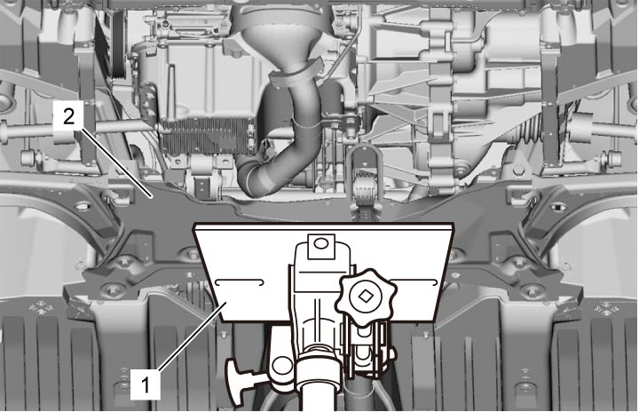
10)Support front suspension frame (2) using transmission jack (1).

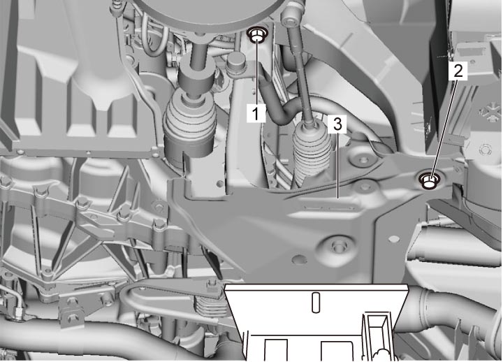
11)Remove suspension frame mounting No.1 bolts (1) and No.2 bolts (2), and then lower transmission jack to remove suspension frame (3) together with stabilizer bar, torque rod(s) and steering gear case from vehicle body.
12)Remove steering gear case assembly from front suspension frame.
13)Remove torque rod(s) from front suspension frame.
•M16A model:
•K14C model:
•D16AA model:
•K14C model:
•D16AA model:
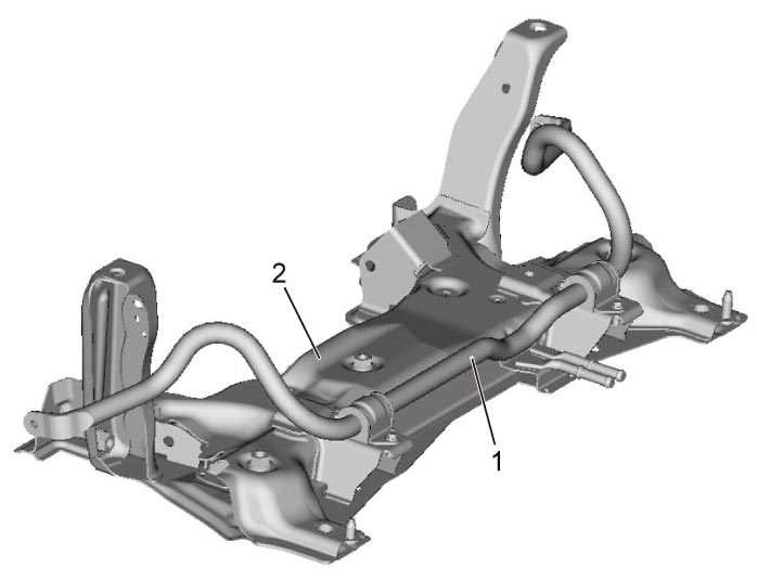
14)Remove front stabilizer bar (1) and bushings from front suspension frame (2).
Installation
1)Install front stabilizer bar (1), bushings (2) and mounting brackets (3) to front suspension frame as shown in figure.
NOTE:
•Install stabilizer bar with identification painting (5) facing up.
•Install stabilizer bar bushing with its end closely fitted against ring (4) of stabilizer bar.
•Install stabilizer bar bushing with its end closely fitted against ring (4) of stabilizer bar.
2)Tighten stabilizer bar mounting bracket bolts to specified torque in numerical order (“1” – “2”) as shown in figure.
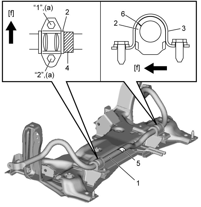
| [f]: | Forward | 6. | Slit |
3)Install torque rod(s) to front suspension frame.
•M16A model:
•K14C model:
•D16AA model:
•K14C model:
•D16AA model:
4)Install steering gear case assembly to front suspension frame.
5)Put front suspension frame (2) on transmission jack (1) and raise jack.
6)Align right and left bosses (1) of front suspension frame with holes (2) in vehicle body.
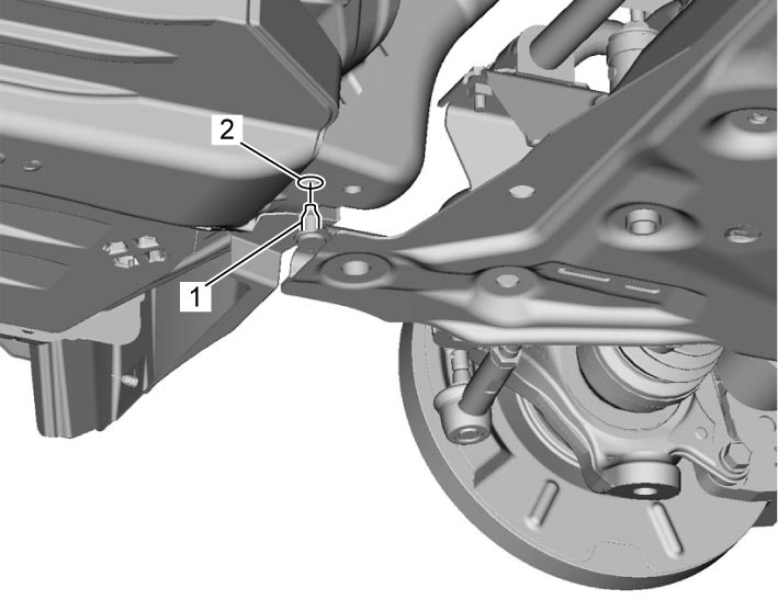
7)Install new suspension frame mounting No.1 bolts (1) and No.2 bolts (2) and tighten them to specified torques.
Suspension frame mounting No.2 bolt (b): 145 N·m (14.8 kgf-m, 107.0 lbf-ft)
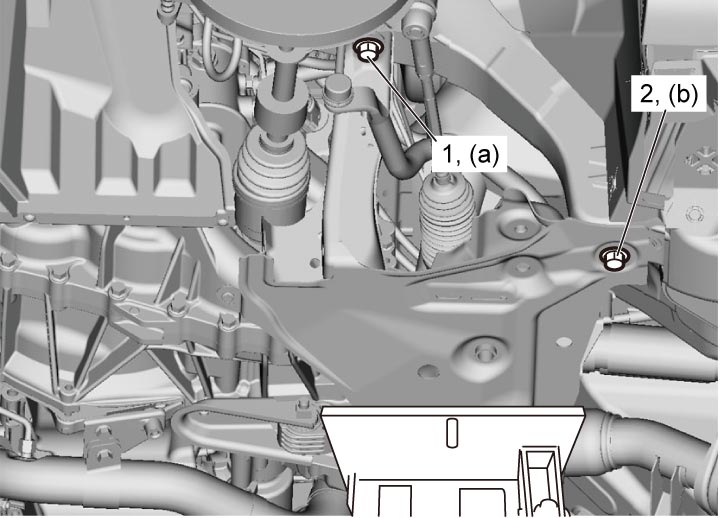
Tightening torque
Suspension frame mounting No.1 bolt (a): 95 N·m (9.7 kgf-m, 70.0 lbf-ft)Suspension frame mounting No.2 bolt (b): 145 N·m (14.8 kgf-m, 107.0 lbf-ft)
8)Lower transmission jack.
9)Install torque rod bolts to specified torque.
•M16A model:
•K14C model:
•D16AA model:
•K14C model:
•D16AA model:
10)Install suspension arm to front suspension frame. Then finger-tighten new suspension arm front bushing bolts and suspension arm rear bushing bolts temporarily by hand.
11)Connect suspension arm joint to steering knuckle.
12)Connect tie-rod end to steering knuckle.
13)Connect stabilizer joint to stabilizer bar.
14)Install muffler mounting to front suspension frame.
•M16A model:
•K14C model:
•D16AA model:
•K14C model:
•D16AA model:
15)Install engine undercovers.
16)Install front wheels and tighten wheel bolts to specified torque.
17)Connect steering lower shaft to pinion shaft.
18)Lower hoist and bounce vehicle up and down several times to stabilize suspension. And then, tighten suspension arm front bolts and rear bolts to specified torque.
19)Connect negative (–) cable at battery.
20)Check front wheel alignment.