A/T Assembly Disassembly
Precautions: Precautions for Diagnosing Trouble · Precautions for Disassembly and Reassembly · Precautions for Transmission / Transaxle · General safety (00)
NOTICE:
Contamination and rough handling of the transaxle may cause premature wear, functional problems and damage to parts.
•Thoroughly clean the exterior of the transaxle before disassembling it.
•Keep workbench, tools and hands clean during the service operation.
•Use special care when handling aluminum parts so as not to damage them.
•Keep removed parts free of dust and other foreign material.
•Keep workbench, tools and hands clean during the service operation.
•Use special care when handling aluminum parts so as not to damage them.
•Keep removed parts free of dust and other foreign material.
1)Drain ATF before overhauling. 
2)Remove TCM.
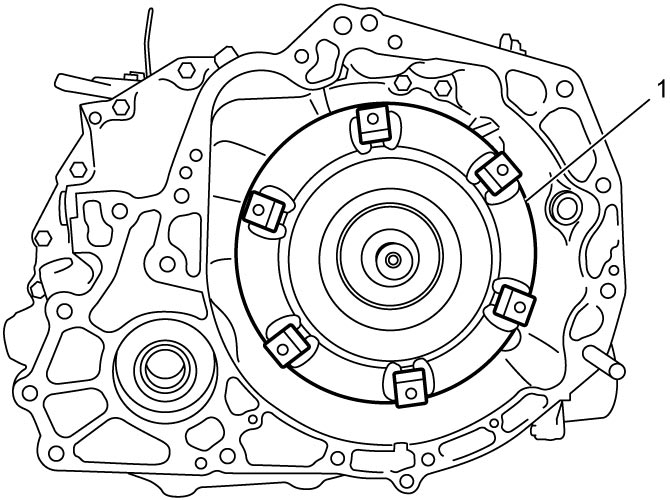
3)Remove torque converter (1) by pulling it out of the transaxle as straight as possible to prevent oil seal lip from damage.

4)Disconnect breather hose (1) and breather plug (2), if necessary.
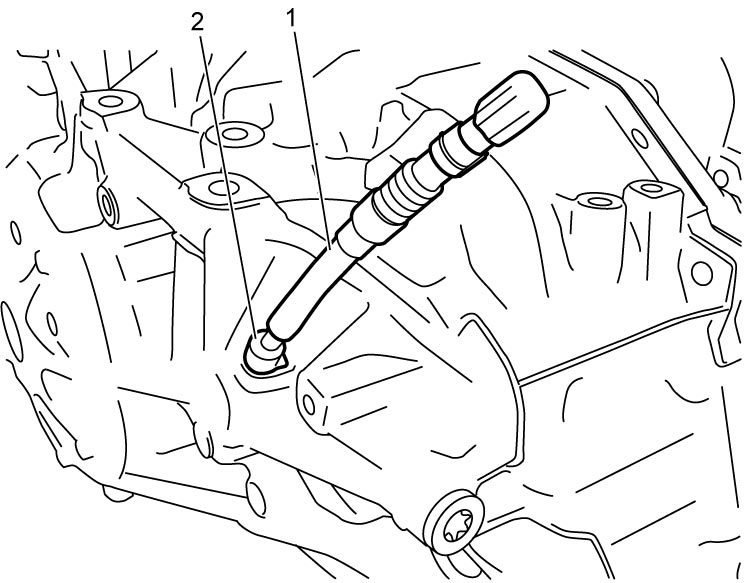
5)Remove A/T hook and harness brackets, if necessary.
6)Remove select cable bracket and select cable clamp.
7)Remove ATF cooler.
8)Remove valve body assembly.
9)Disconnect input shaft speed sensor connector, and then remove solenoid harness lock plate (1) and solenoid harness with ATF temperature sensor (2).
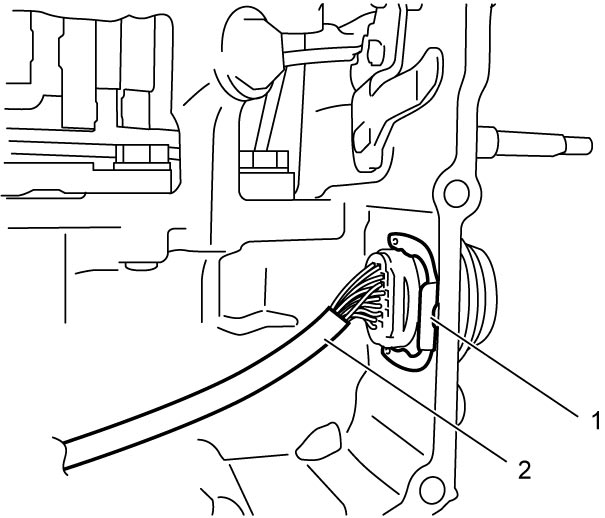
10)Remove input shaft speed sensor.
11)Loosen torque converter housing bolts in numerical order (“1” – “22”) evenly and gradually.
12)Remove torque converter housing (1).
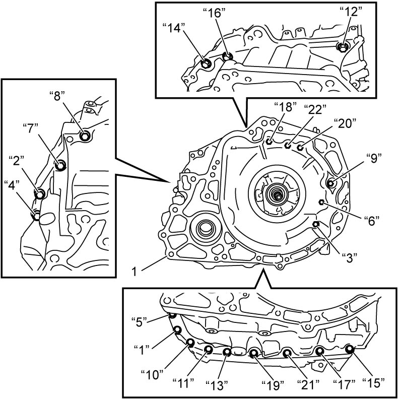
13)Remove transaxle case gaskets (1).
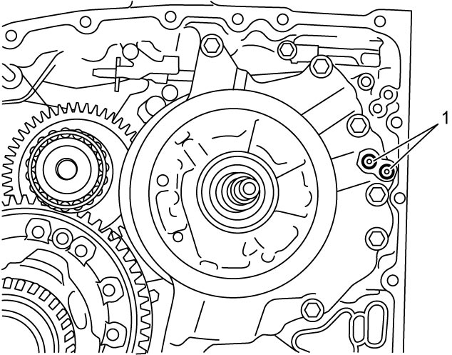
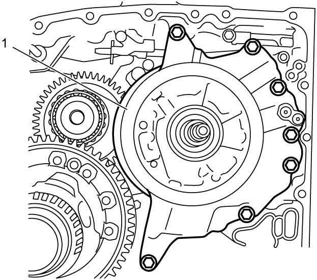
14)Remove oil pump assembly (1).
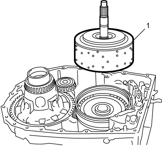
15)Remove reverse clutch assembly and front planetary gear assembly and input shaft (1) all together.
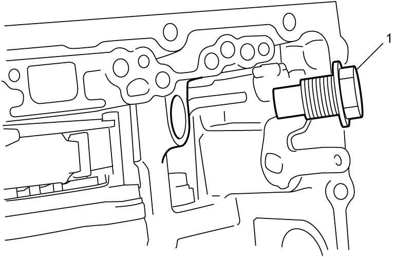
16)Remove B1 brake band anchor bolt (1).
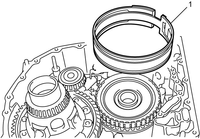
17)Remove B1 brake band (1).
18)Remove B1 brake piston as follows.
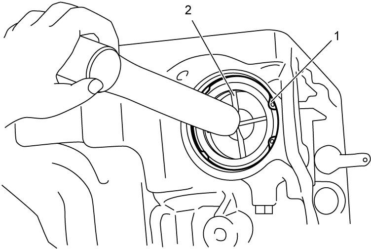
a)Remove snap ring (1) while pushing B1 brake piston cover (2) using hammer or the like.
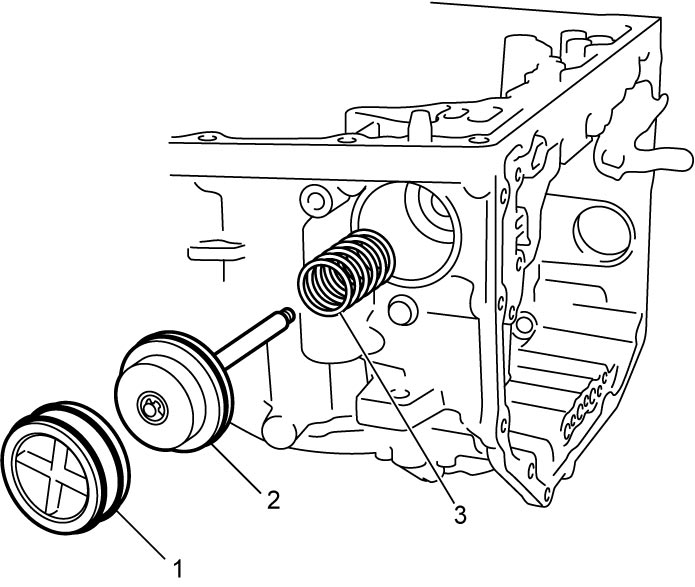
b)Remove B1 brake piston cover (1), B1 brake piston (2) and B1 brake piston spring (3).
19)Remove input shaft thrust bearing (1), input shaft thrust bearing race (2) and forward clutch assembly (3).
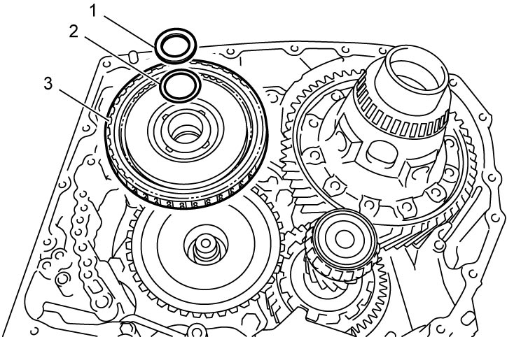
NOTE:
If input shaft thrust bearing is not found, it may have been taken out with input shaft.
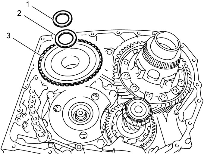
20)Remove sun gear input drum thrust bearing (1), sun gear input drum thrust bearing race (2) and sun gear input drum (3).
21)Remove manual detent spring (1) and spring cover (2).
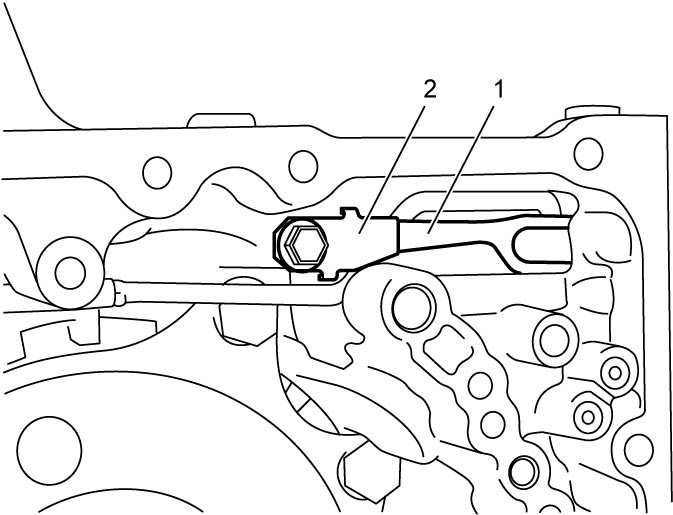
22)Remove spring guide sleeve (1) and spring (2).
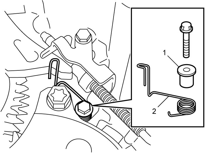
23)Remove parking lock pawl shaft (1) and spring (2).
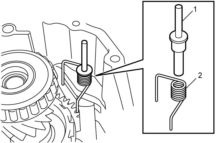
24)Remove parking lock pawl (1) and parking lock pawl bracket (2).
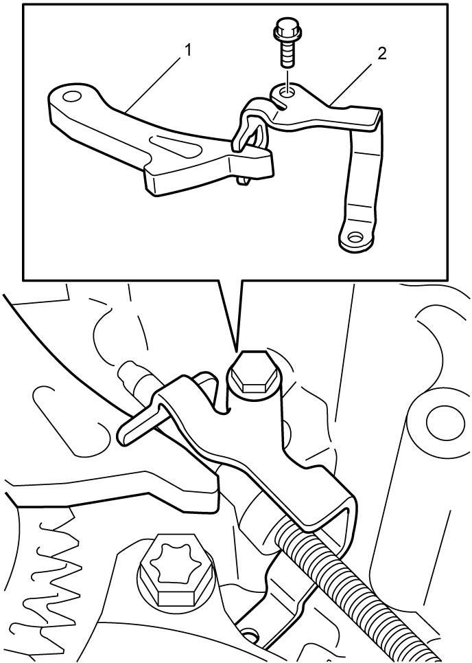
25)Disconnect parking lock rod (1) from manual valve lever (2).
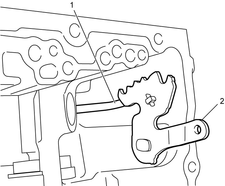
26)Remove manual valve lever (1) and parking lock rod (2).
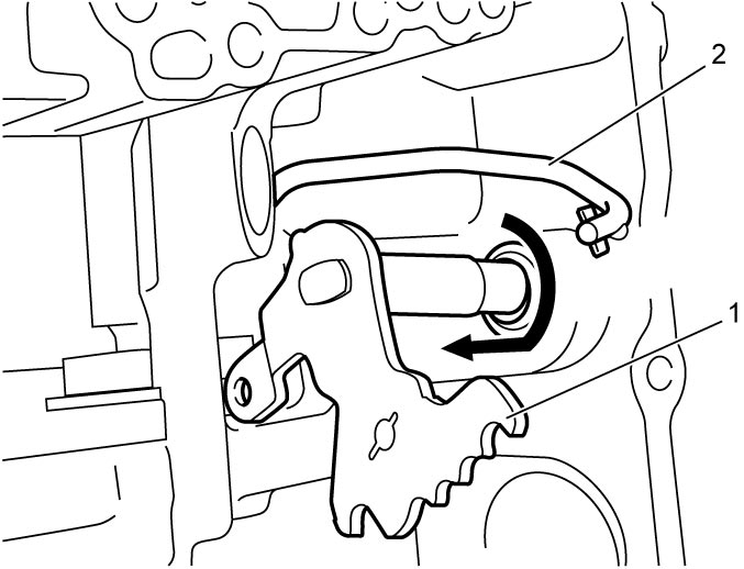
27)Remove parking lock pin (1).
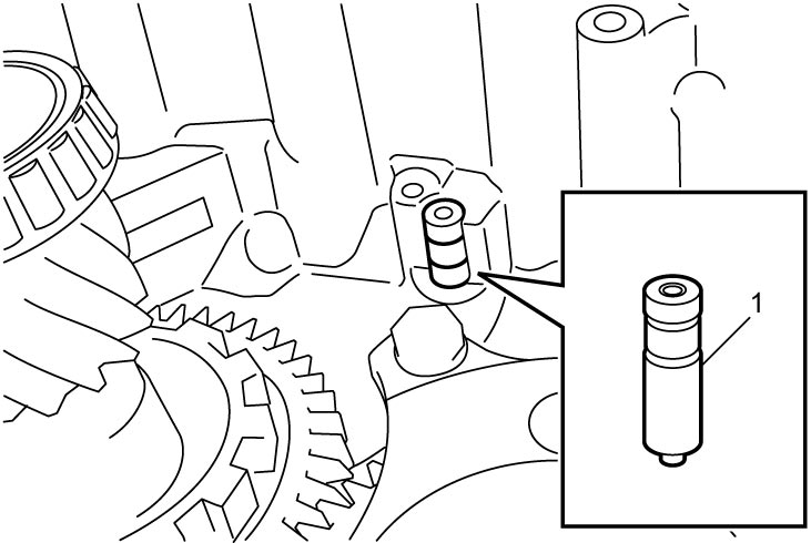
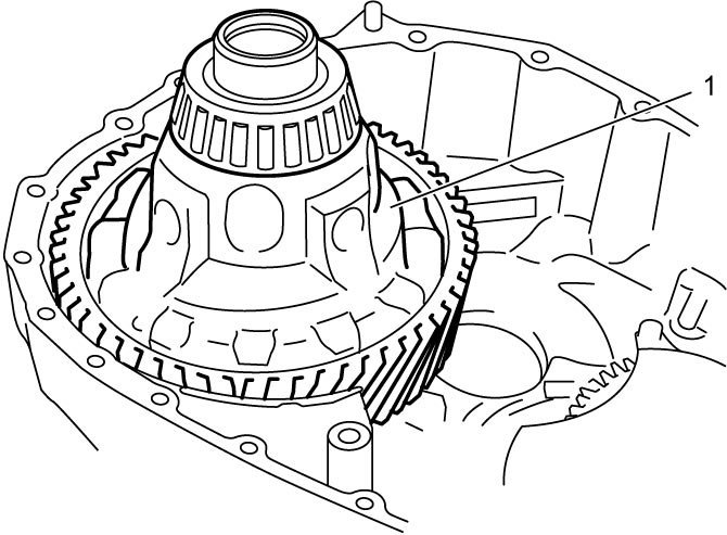
28)Remove pinion and counter driven gear assembly (1).
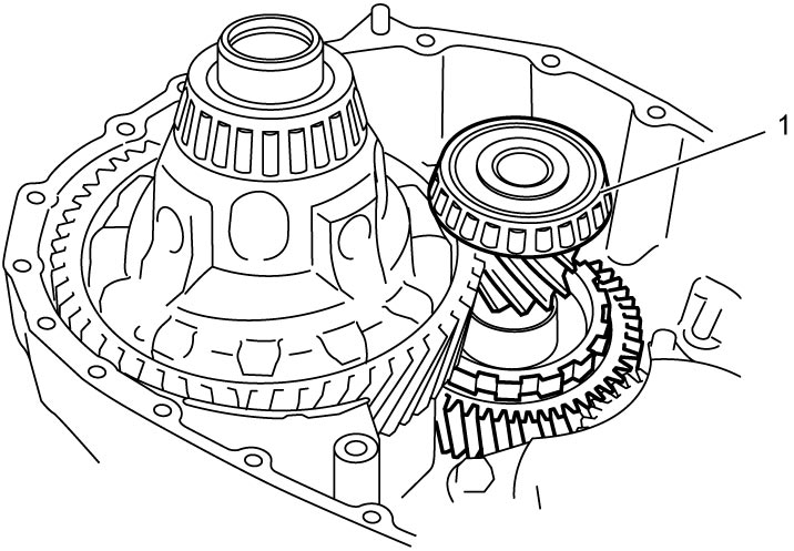
29)Remove differential assembly (1).
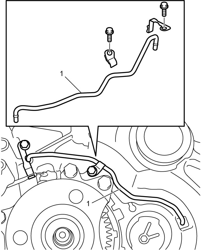
30)Remove lubrication tube (1).
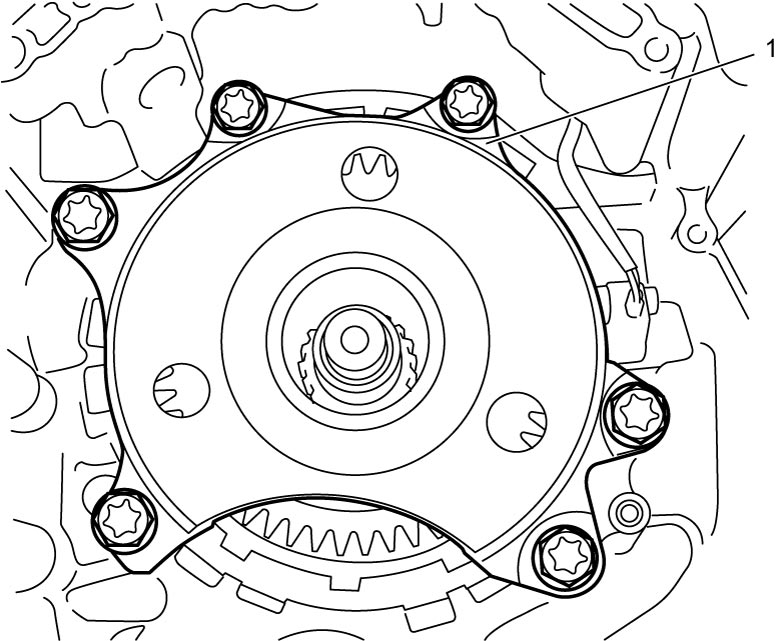
31)Remove counter drive gear assembly (1).
32)Remove output shaft speed sensor.
33)Remove rear planetary sun gear No.1 (1), rear planetary sun gear No.1 thrust bearing (2) and rear planetary sun gear No.1 thrust bearing race (3).
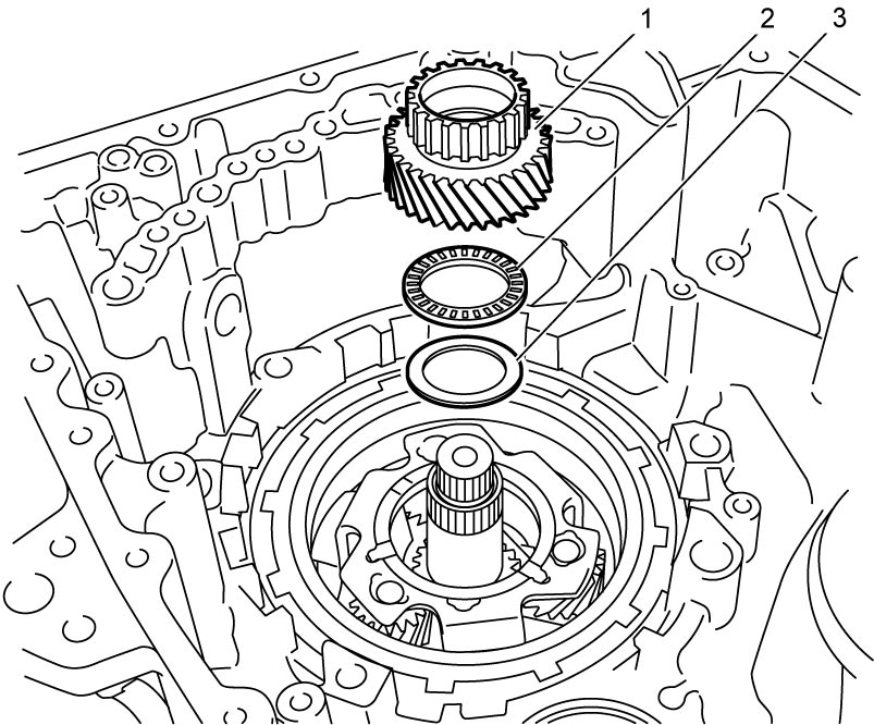
34)Remove rear planetary sun gear No.2 (1).
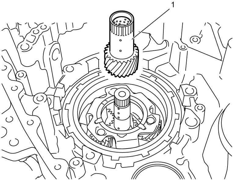
35)Remove 1st and reverse brake snap ring No.2 (1).
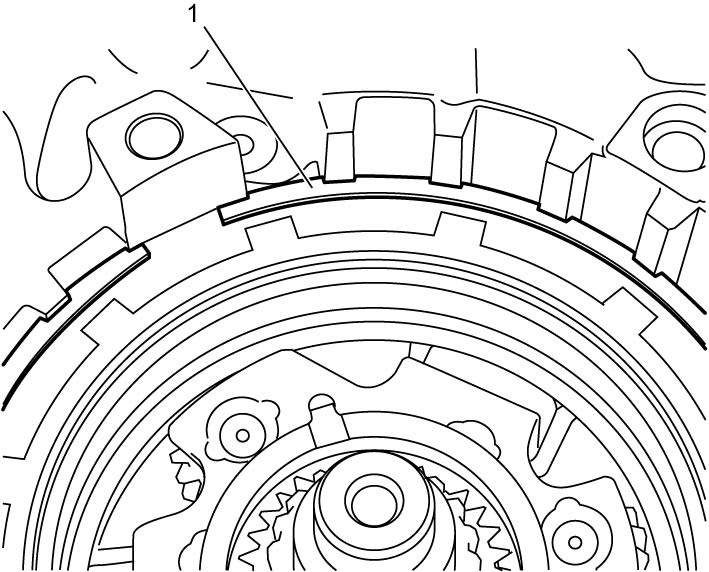
36)Remove rear planetary gear assembly (1) and one-way clutch (2).
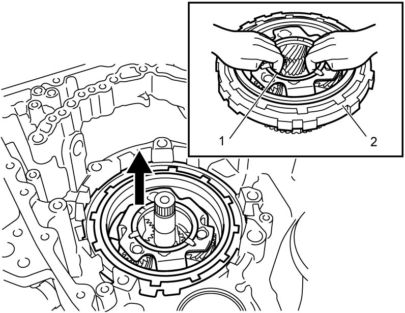
37)Remove rear planetary sun gear No.2 thrust bearing (1) and rear planetary sun gear No.2 thrust bearing races (2).
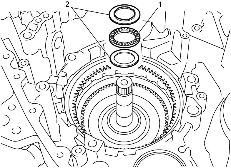
38)Remove 1st and reverse brake snap ring No.1 (1).
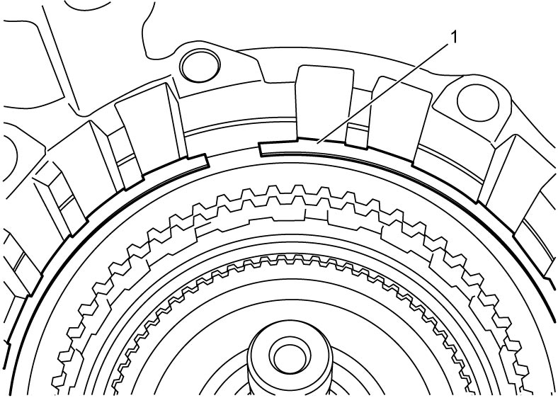
39)Remove 1st and reverse brake disc, 1st and reverse brake retaining plate and 1st and reverse brake separator plate.
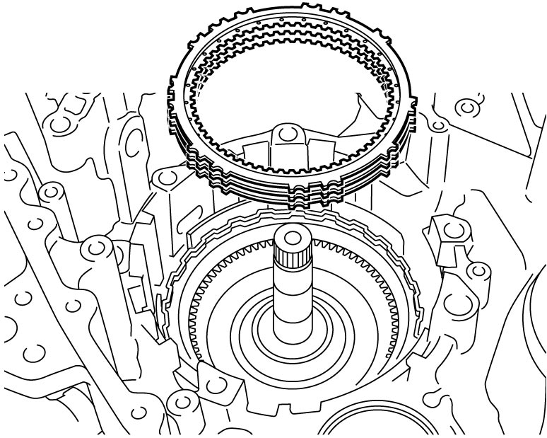
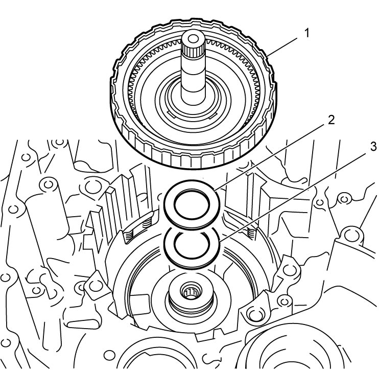
40)Remove direct clutch assembly (1), direct clutch thrust bearing (2) and direct clutch thrust bearing race (3).
41)Remove 1st and reverse brake piston as follows.
a)Remove 1st and reverse brake piston snap ring No.2 (1).
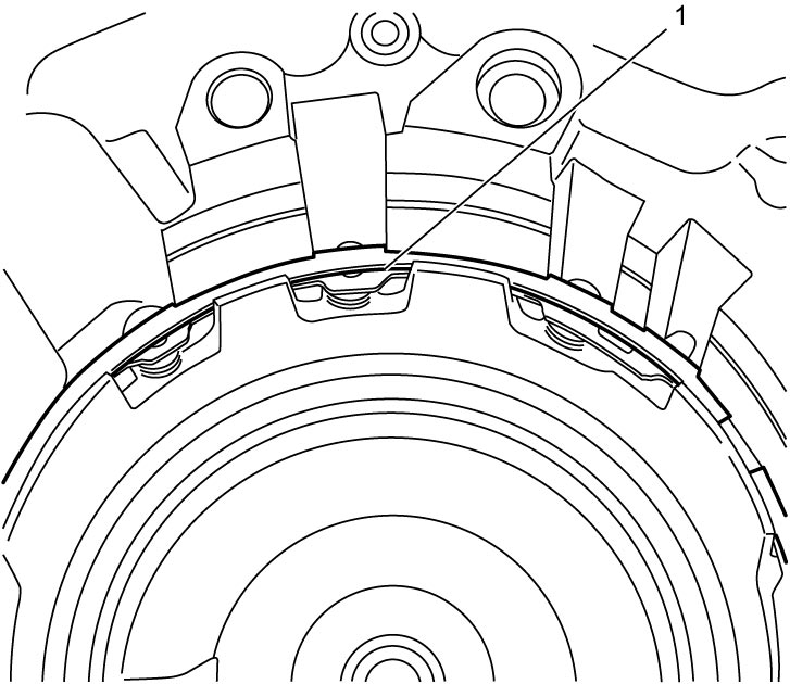
b)Remove 1st and reverse brake return spring (1).
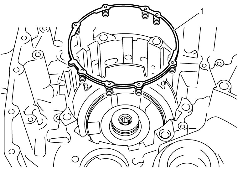
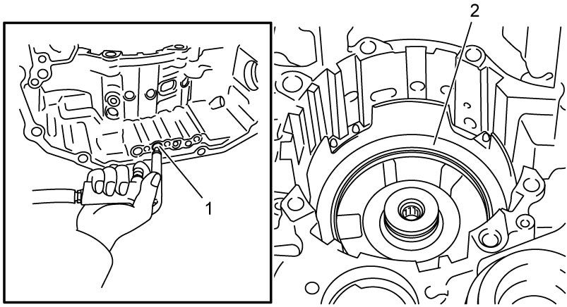
c)Apply compressed air (400 to 800 kPa, 4.1 to 8.2 kgf/cm2, 58.0 to 116 psi) to oil hole (1) of transaxle case to remove 1st and reverse brake piston (2).
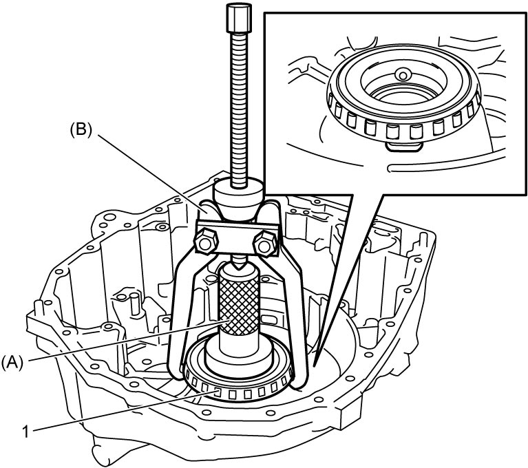
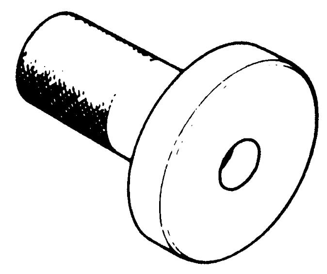
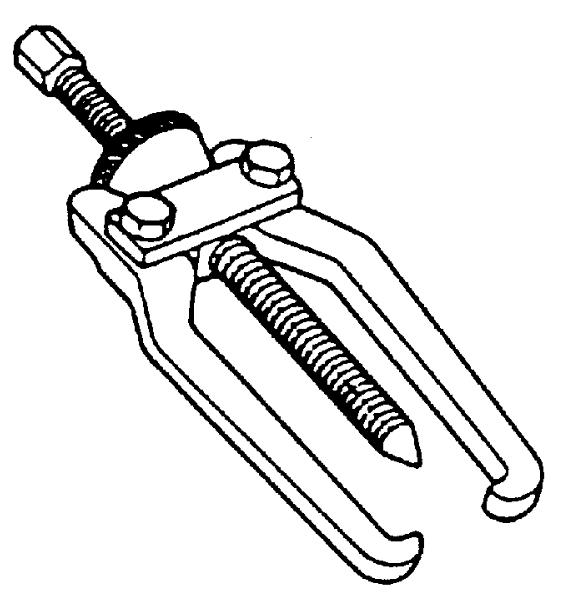
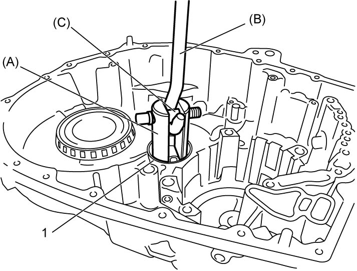
42)Using special tool, remove pinion and counter driven gear left taper roller bearing outer race (1) and shim, if necessary.
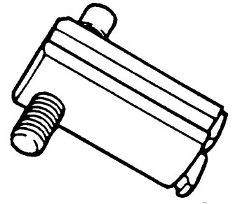
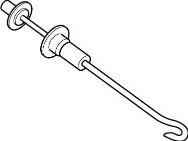
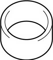
43)Using special tool, remove differential side left taper roller bearing (1), if necessary.