3ZR-FAE LUBRICATION OIL PUMP REMOVAL
CAUTION / NOTICE / HINT
The necessary procedures (adjustment, calibration, initialization, or registration) that must be performed after parts are removed, installed, or replaced during the oil pump assembly removal/ installation are shown below.
| Replacement Part or Procedure | Necessary Procedure | Effect/Inoperative when not Performed | Link |
|---|---|---|---|
| Replacement of CVT fluid | ATF thermal degradation estimate reset | The value of the Data List item "ATF thermal Degradation Estimate" is not estimated correctly | ( ) |
| Front wheel alignment adjustment | Perform the following procedures in the order shown:
1.
Clear zero point calibration data and store system information 2.
Perform yaw rate and acceleration sensor zero point calibration and store system information |
·
VSC disabled or malfunctions ·
DTCs are stored ·
Slip indicator light illuminates ·
ABS warning light illuminates |
()
|
- HINT:
-
When the cable is disconnected / reconnected to the battery terminal, systems temporarily stop operating. However, each system has a function that completes learning the first time the system is used.
- ·
Learning completes when vehicle is driven
Effect/Inoperative Function When Necessary Procedures are not Performed Necessary Procedures Link *1: When performing learning using the GTS
Click here(
)
Simple intelligent parking assist system*1 Drive the vehicle straight ahead at 35 km/h (22 mph) or more for 5 second or more. ( )
·Learning completes when vehicle is operated normally
Effect/Inoperative Function When Necessary Procedures are not Performed Necessary Procedures Link Power door lock control system
·Back door opener
Perform door unlock operation with door control switch or electrical key transmitter sub-assembly switch. ( )
Air conditioning system After the ignition switch is turned to ON, the servo motor standard position is recognized. -
PROCEDURE

 1.INSTALL ENGINE TO ENGINE STAND
2.REMOVE ENGINE HANGER
22210
3.REMOVE THROTTLE BODY ASSEMBLY
22271
4.REMOVE THROTTLE BODY GASKET
17650
5.REMOVE VACUUM SWITCHING VALVE ASSEMBLY
12261
6.DISCONNECT VENTILATION HOSE
17111
7.REMOVE INTAKE MANIFOLD
8.REMOVE WIRE HARNESS CLAMP BRACKET
23901
9.DISCONNECT FUEL TUBE SUB-ASSEMBLY
23807
10.REMOVE FUEL DELIVERY PIPE SUB-ASSEMBLY
23807V
11.REMOVE NO. 1 DELIVERY PIPE SPACER
23291
12.REMOVE INJECTOR VIBRATION INSULATOR
23250
13.REMOVE FUEL INJECTOR ASSEMBLY
11452
14.REMOVE ENGINE OIL LEVEL DIPSTICK GUIDE
17167
15.REMOVE NO. 1 EXHAUST MANIFOLD HEAT INSULATOR
17118
16.REMOVE MANIFOLD STAY
17141
17.REMOVE EXHAUST MANIFOLD
12261
18.REMOVE VENTILATION HOSE
16267
19.DISCONNECT NO. 3 WATER BY-PASS HOSE
16261
20.REMOVE WATER BY-PASS HOSE
16262
21.REMOVE WATER INLET HOSE
16321
22.SEPARATE WATER INLET
16331A
23.REMOVE THERMOSTAT
19500
24.REMOVE IGNITION COIL ASSEMBLY
29300
25.REMOVE VACUUM PUMP ASSEMBLY
12551A
26.REMOVE NO. 1 VACUUM PUMP BRACKET
16620
27.REMOVE V-RIBBED BELT TENSIONER ASSEMBLY
11201
28.REMOVE CYLINDER HEAD COVER SUB-ASSEMBLY
11213
29.REMOVE CYLINDER HEAD COVER GASKET
30.SET NO. 1 CYLINDER TO TDC/COMPRESSION
13471
31.REMOVE CRANKSHAFT PULLEY
13540
32.REMOVE NO. 1 CHAIN TENSIONER ASSEMBLY
11302
33.REMOVE TIMING CHAIN COVER SUB-ASSEMBLY
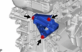
Remove the 3 bolts and engine mounting bracket RH from the timing chain cover sub-assembly.
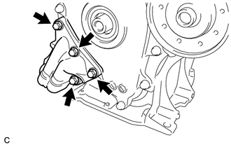
Remove the 4 bolts and oil filter bracket from the timing chain cover sub-assembly.
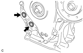
Remove the 2 O-rings from the timing chain cover sub-assembly.
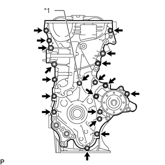
| *1 | Seal Washer |
Remove the 19 bolts and seal washer from the timing chain cover sub-assembly.
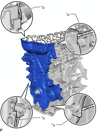
| *a | Protective Tape |
Remove the timing chain cover sub-assembly by prying between the timing chain cover sub-assembly and cylinder head sub-assembly, camshaft housing sub-assembly, cylinder block sub-assembly and stiffening crankcase assembly with a screwdriver as shown in the illustration.
- NOTICE:
-
Be careful not to damage the contact surfaces of the cylinder head sub-assembly, camshaft housing sub-assembly, cylinder block sub-assembly, stiffening crankcase assembly and timing chain cover sub-assembly.
- HINT:
-
Tape the screwdriver tip before use.
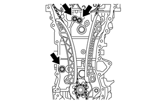
Remove the O-ring from the cylinder block sub-assembly.
Remove the 2 O-rings from the cylinder head sub-assembly.
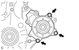
Remove the 3 bolts and engine water pump assembly from the timing chain cover sub-assembly.
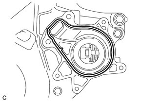
Remove the gasket from the timing chain cover sub-assembly.
11302A
34.REMOVE TIMING CHAIN COVER OIL SEAL
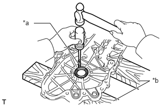
| *a | Protective Tape |
| *b | Wooden Block |
Place the timing chain cover sub-assembly on wooden blocks.
Using a screwdriver, tap out the timing chain cover oil seal.
- NOTICE:
-
Do not damage the surface of the timing chain cover oil seal press fit hole.
- HINT:
-
Tape the screwdriver tip before use.
13559
35.REMOVE CHAIN TENSIONER SLIPPER
13561
36.REMOVE NO. 1 CHAIN VIBRATION DAMPER
13506
37.REMOVE CHAIN SUB-ASSEMBLY
13521
38.REMOVE CRANKSHAFT TIMING SPROCKET
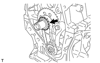
Remove the crankshaft timing sprocket.
13507
39.REMOVE NO. 2 CHAIN SUB-ASSEMBLY
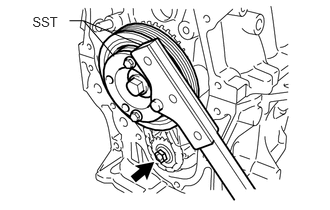
Temporarily install the crankshaft pulley with the crankshaft pulley bolt.
Using SST, hold the crankshaft pulley. Then remove the oil pump drive shaft gear nut.
- SST
- 09330-00021 09213-54015
- HINT:
-
Part number of installation bolt for SST (crankshaft pulley holding tool): 91551-00850 (quantity: 2)
Remove SST, the crankshaft pulley bolt and crankshaft pulley.
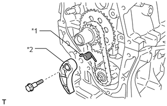
| *1 | Chain Damper Spring |
| *2 | Chain Tensioner Plate |
Remove the bolt, chain tensioner plate and chain damper spring.
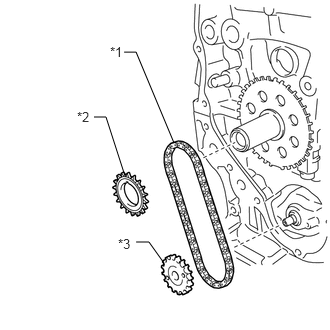
| *1 | No. 2 Chain Sub-assembly |
| *2 | Oil Pump Drive Gear |
| *3 | Oil Pump Drive Shaft Gear |
Remove the oil pump drive gear, oil pump drive shaft gear and No. 2 chain sub-assembly.
12102A
40.REMOVE NO. 2 OIL PAN SUB-ASSEMBLY
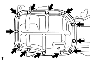
Remove the 10 bolts and 2 nuts.
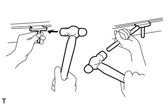
Insert the blade of an oil pan seal cutter between the stiffening crankcase assembly and No. 2 oil pan sub-assembly. Cut through the sealer and remove the No. 2 oil pan sub-assembly.
- NOTICE:
- ·
Be careful not to damage the surface of the No. 2 oil pan sub-assembly which contacts the stiffening crankcase assembly.
·Be careful not to damage the stiffening crankcase assembly flange.
15100
41.REMOVE OIL PUMP ASSEMBLY
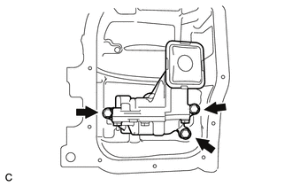
Remove the 3 bolts and oil pump assembly from the stiffening crankcase assembly.